4-20
PERFORMANCE VERIFICATION PROCEDURE
4. Power supply voltage range
•**
Ail models
*'•
Th^ test checks the correct operation of the
ScopeMeter within the boundaries of the DC supply
voltage.
Test equipment:
Philips PE 1537 Power Supply 0-40V/0-1A
Tektronix SO 503 Constant Ampittude Sine Wave Generator
5 mm Power Jack connector plug with attached cable {for example order 4622
321 20125)
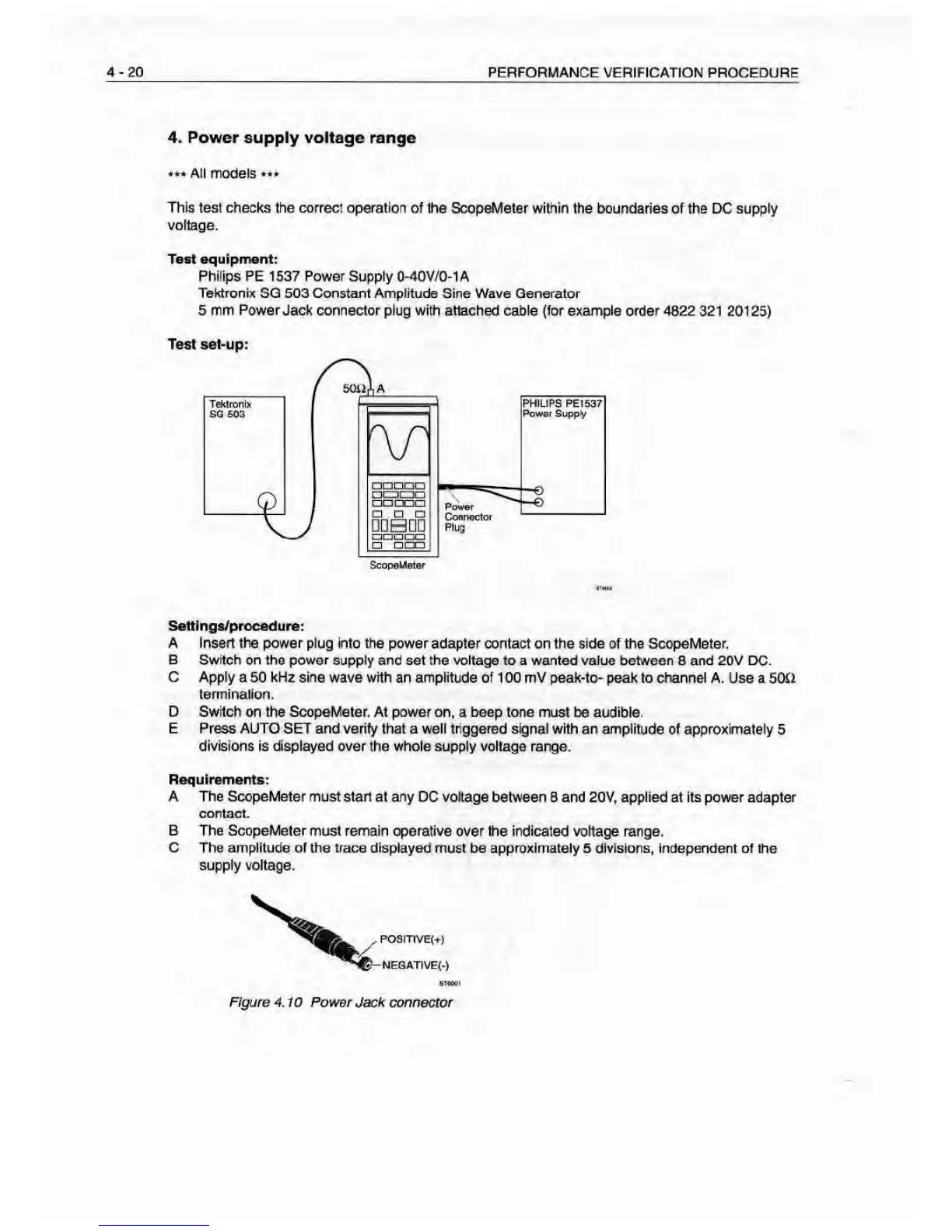
Test
set-up:
ScoQ«Uetar
Settl ngs/proeedure
:
A Insert the power
plug into the power adapter contact on the side of the ScopeMeter.
B Switch on the power
supply and set the voltage to a wanted value between 8 and 20V DC.
C
Apply a 50 kHz
sine
wave v/tth an amplitude of 100 mV peak-to- peak to channel
A.
Use
a SOD
termination.
D Swich on the ScopeMeter. At power on, a beep tone must
be
audible.
E Press AUTO SET and verify that a well triggered signal with an amplitude of approximately
5
divisions is displayed over the whole supply voltage range.
Requirements:
A The ScopeMeter must start
at any DC voltage between 3 and 20V, applied at Its power adapter
contact.
B The ScopeMeter must remain operative
over the indicated voltage range.
C The amplitude of the trace displayed
must be approximately 5 divisions, independent of the
supply voltage.
Figure 4.10 Power Jack connector