5-2
CALIBRATION
ADJUSTMENT PROCEDURE
Cables and terminators for
the generators {all 6NC t^e]
•
Standard banana test leads
(two banana lest leads are delivered
wltti the ScopeMeter)
•
BNC (female)-lo-banana (mate) (delivered
with the ScopeMeter)
•
The red and grey probes,
delivered with the ScopeMeter.
5.3 ENTERING
THE CAUBRATION
PROCEDURE
The Calibration Adjustment Procedure Is operated
via built-in sequences. Before you can activate
a
calibration
sequence, you must first connect a 1 2V DC programming
vohage to the ScopeMeter. To
do this, Rrst
remove the bettery pack. See section 6.2.1.
17
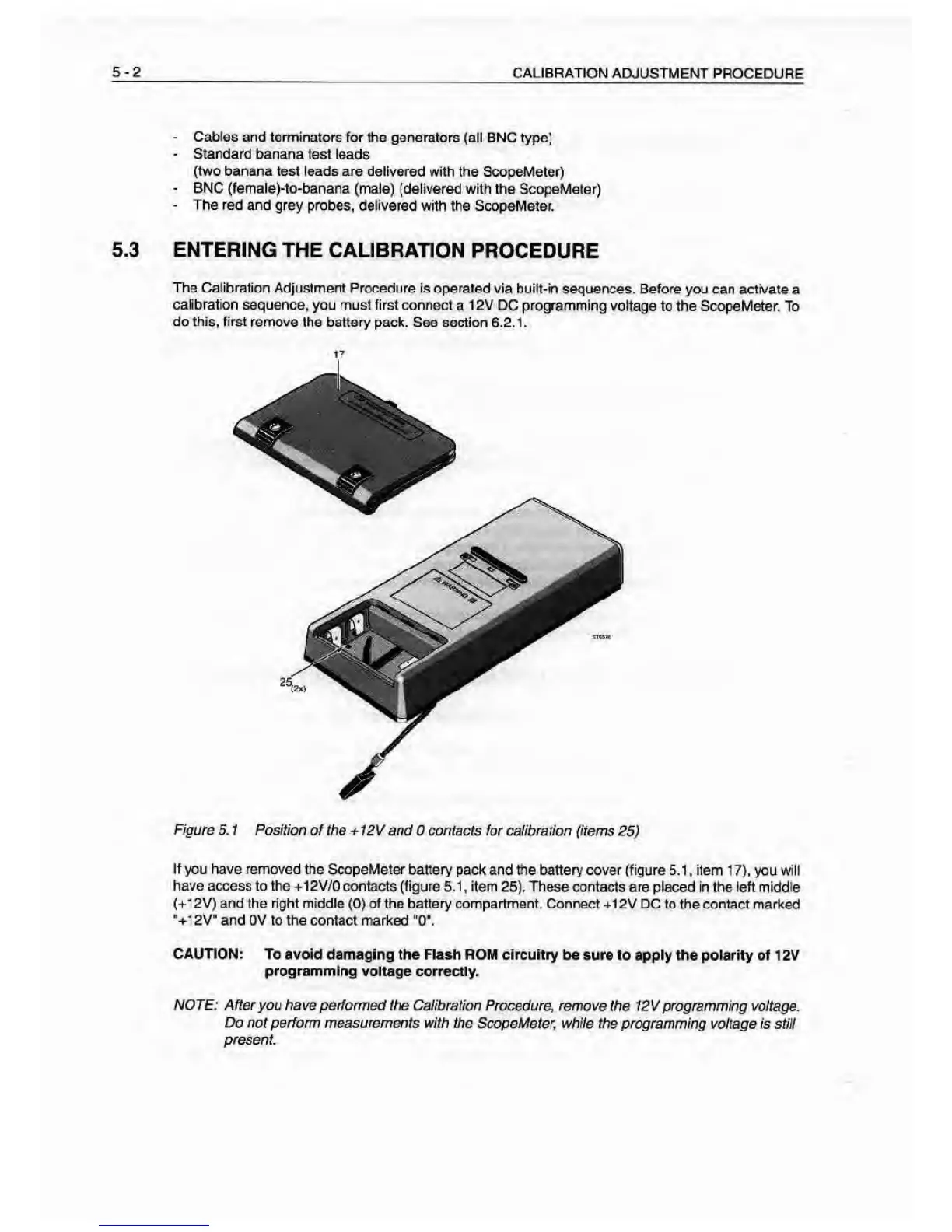
Figure 5. 1 Position
of the
-t‘12V
and 0 contacts for calibration (items
25)
If you have removed the ScopeMeter battery
pack and the battery cover (figure 5.1
,
item
17), you
will
have access to the -»-12V/0 contacts (figure
5.1
,
item
25). These contacts are placed in the left middle
(+12V) and the right middle
(0)
of the
battery
compartment. Connect +12V DC to the cor^tact marked
•+1
2V" and OV to the contact marked
“0".
CAUTION:
To avoid damaging the Flash ROM circuitry be sure
to apply the polarity of 1 2V
programming voltage correctly.
NOTE: After
you have performed the Calibration Procedure, remove
the 12V
programming
voltage.
Do not perform measurements with the ScopeMeter, while
the programming voltage is stiH
present