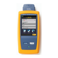
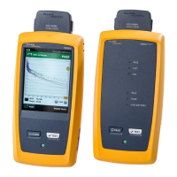
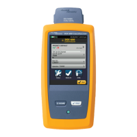
DSP-4000 Series
Users Manual
7-28
Table 7-1. Identifying Cable Faults
Test Failure Likely Causes of Failure
Wire map: open Wires connected to wrong pins at connector or punchdown
blocks.
Faulty connections.
Cables routed to the wrong location.
Wires broken by stress at connections.
Damaged connector.
Cuts or breaks in cable.
Wire map: split pair Wires connected to wrong pins at connector or punchdown
blocks.
Wire map: reversed pairs Wires connected to wrong pins at connector or punchdown
blocks.
Wire map: crossed pairs Wires connected to wrong pins at connectors or punchdown
blocks.
Mix of 568A and 568B wiring standards (1, 2 and 3, 6 crossed).
Crossover cables used where not needed (1, 2 and 3, 6 crossed).
 Loading...


