Getting Started
Saving Test Reports
2
2-11
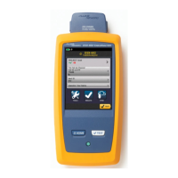
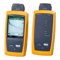
1. Attach the appropriate link interface adapters to the main and remote units.
Refer to the table in the Appendix.
2. Turn the remote’s rotary switch to ON.
3. Connect the remote to the far end of the cable link. For channel testing,
connect using the network equipment patch cord.
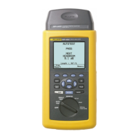
4. Turn the rotary switch on the main unit to AUTOTEST.
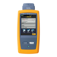
5. Verify that the settings displayed are correct. You can change these settings in
the SETUP mode.
6. Connect the test tool to the near end of the cable link. For channel testing,
connect using the network equipment patch cord.
7. Press T to start the Autotest.
Saving Test Reports
When an Autotest is complete, you can save the results by pressing S. Use
the alphanumeric display to enter a cable identification for the report; then press
S again. See Chapter 3 for details.
To configure the test tool’s auto increment or auto sequence function, see
“Automatically Incrementing the Cable Identification” in this chapter. You can
view and delete saved Autotest reports in the SPECIAL FUNCTIONS mode.
See the CableManager Appendix for information on uploaded reports to a PC.
 Loading...


