Basic Cable Testing
Attenuation (Insertion Loss)
7
7-7
Attenuation (Insertion Loss)
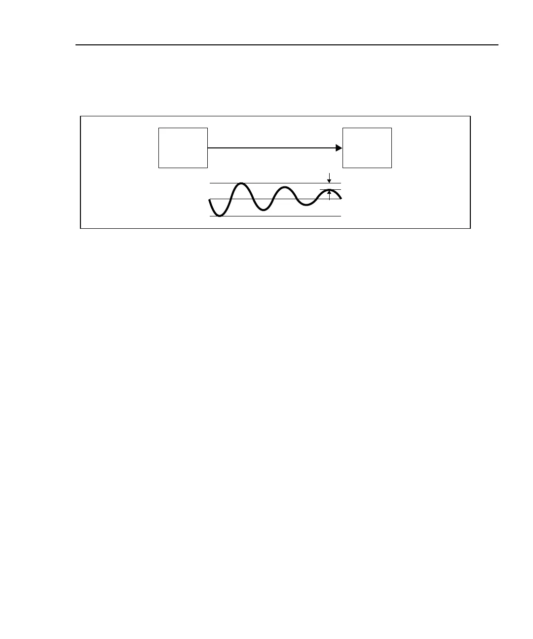
Attenuation is a decrease in signal strength over the length of a cable, as shown in
Figure 7-6.
Signal
Source
Signal
Receiver
Cable
V
OUT
VIN
Loss
oy30f.eps
Figure 7-6. Attenuation of a Signal
Attenuation is caused by a loss of electrical energy in the resistance of the cable
wire and by leakage of energy through the cable’s insulating material. This loss of
energy is expressed in decibels. Lower attenuation values correspond to better
cable performance. For example, when comparing the performance of two cables
at a particular frequency, a cable with an attenuation of 10 dB performs better than
a cable with an attenuation of 20 dB.
Cable attenuation is determined by the cable’s construction, length, and the
frequencies of the signals sent through the cable. At higher frequencies, the skin
effect and the cable’s inductance and capacitance cause attenuation to increase.

 Loading...