DSP-4000 Series
Users Manual
7-6
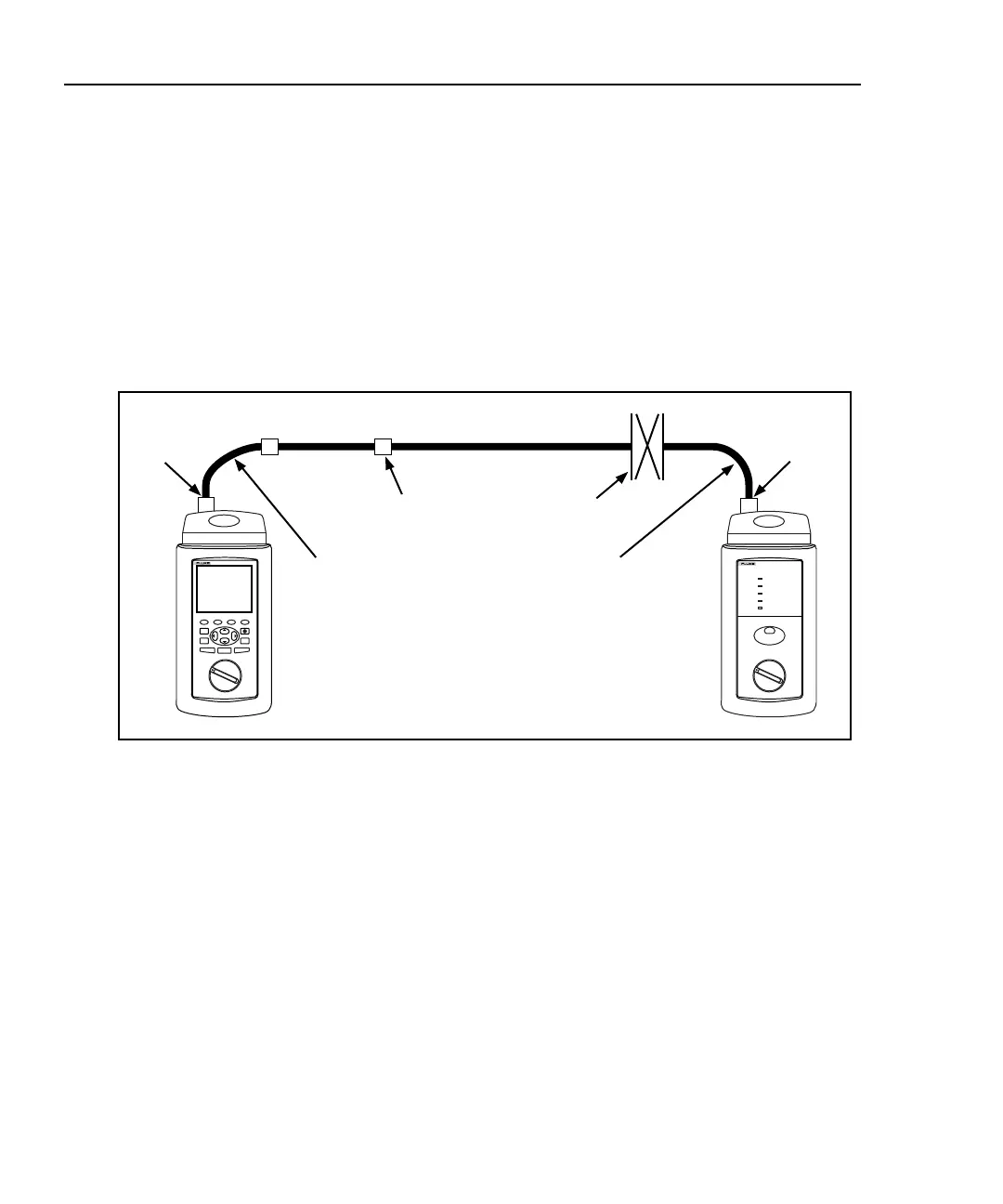
A channel includes the transition connectors and equipment patch cables added to
a basic link segment. The channel should be tested from end to end to verify the
performance of all the components. In this case, you use the equipment patch
cables to connect your test tool to the channel, as shown in Figure 7-5. TSB-67
defines the channel as a basic link plus one extra transition connector at each end
and up to 10 meters of equipment patch cables. Because of the extra connectors
and patch cables, the test limits for a channel are looser than those for the basic
link.
A channel with just one connector at each end resembles a basic link; however,
you would use a channel test standard if you are using the network equipment’s
patch cables to connect to your test tool.
Network
equipment
patch cable
Network
equipment
patch cable
Horizontal cabling
Channel
Horizontal
cross connect
Test Tool
Smart
Remote
TALK
Start
channel
End
channel
Transition
connector
oy69f.eps
Figure 7-5. Channel Test Connections

 Loading...