Basic Cable Testing
Basic Link and Channel Connections
7
7-5
Basic Link and Channel Connections
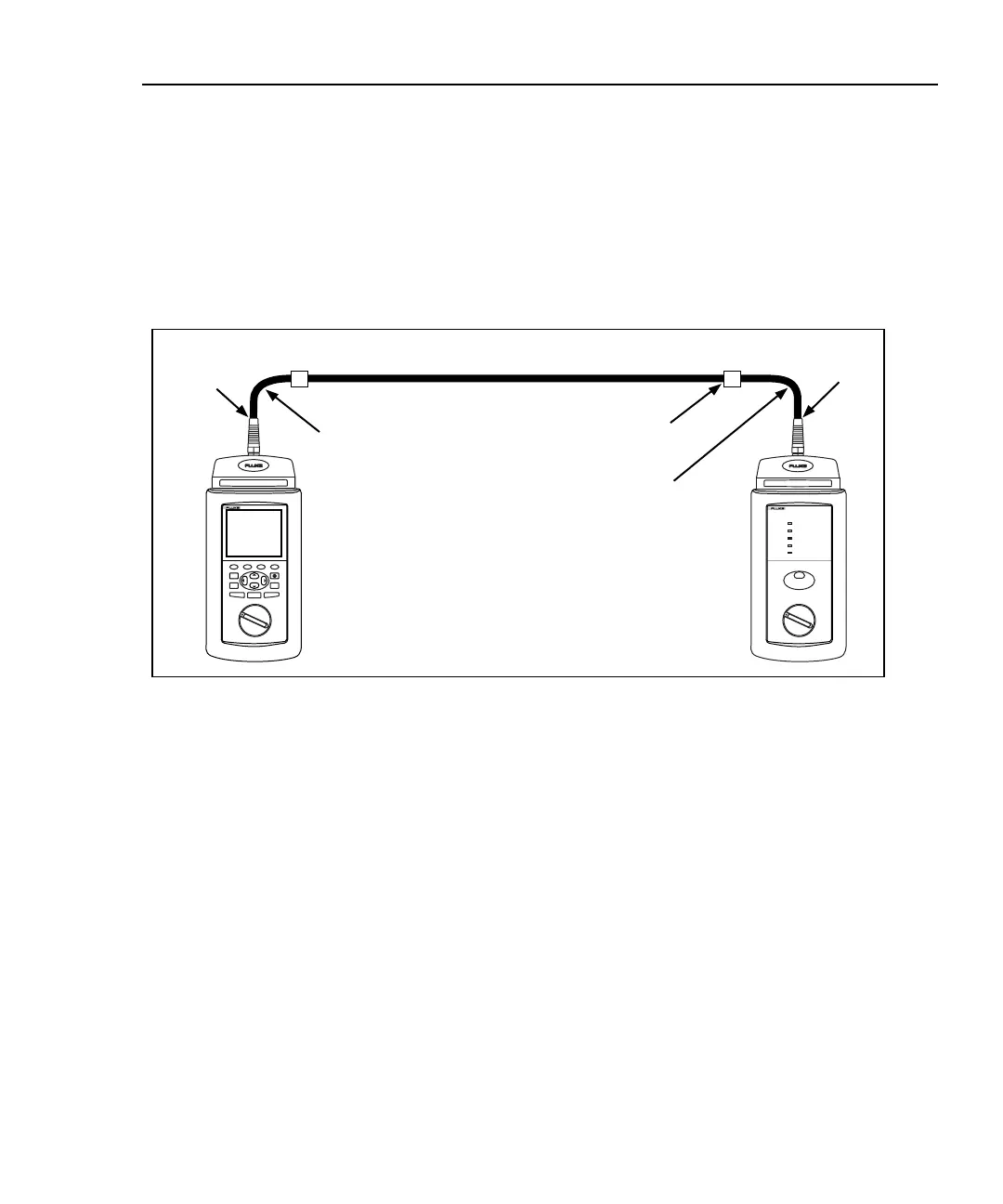
The cable links you test may or may not include equipment patch cables and extra
transition connections in the telecommunications closet and work area. For
example, cable installers are often responsible only for the permanent cable
installed between the closet and the first wall outlet in the work area. This segment
of cable is the basic link, shown in Figure 7-4. As defined in TSB-67, the basic
link consists of up to 90 m of horizontal cable, one transition connector at each
end, and two test equipment patch cables of no more than 2 m each.
Test equipment
patch cable
Test equipment
patch cable
Horizontal cabling
Basic link
Patch panel
connection
Test Tool
Smart
Remote
TALK
Start
basic link
End
basic link
oy73f.eps
Figure 7-4. Basic Link Test Connections

 Loading...