Owner’s Manual Page 55Engines and Instrumentation - Section E
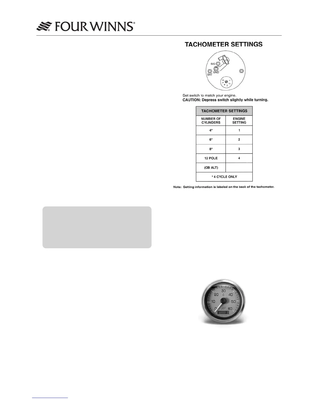
Figure E-3: Tachometer Settings
The tachometer/hour meter combination gauge
allows for hour meter viewing at the helm. See Figure
E-4. The hour meter provides a numeric record of
elapsed engine operating time. This information is
important in determining scheduled maintenance
intervals, ship’s log data, cruise information, etc.
The hour meter is connected to the ignition switch.
Be sure the ignition switch is in the OFF position
when the engine is not operating or the hour meter
will record additional time.
Figure E-4: Tachometer/Hour Meter
C. Trim Tab Maintenance
Checktheuidlevelofthetrimtabreservoiroften.
Alwayskeeptheuidlevelbetweenthedesignated
marks on the trim tab pump-reservoir. Refer to the
manufacturersinformationforspecicationsonthetype
ofuidtobeusedandotheroperationandmainte-
nance information.
E - 7 INSTRUMENTATION
The helm stations on Four Winns
®
models are
equipped with a complete set of individual engine in-
strument gauges. These instrument gauges allow
the boat operator to constantly monitor the operational
condition of the engine. Close observation of these
instrument gauges could save the engine from
damage.
A. Tachometer/Hour Meter Combination Gauge
The tachometer indicates the speed of the engine in
revolutions per minute (RPM). This speed is not the
boat speed or necessarily the speed of the propeller.
The tachometer may not register zero with the
ignition key in the OFF position.
NOTICE
Never exceed the maximum recommended
operating RPM of your engine. Maintaining
maximum, or close to maximum RPM for
extended periods can reduce the life of the
engine.
Some engines are equipped with devices that limit
engine RPM in accordance with the oil pressure,
o
r engine temperature. Refer to the engine manual
included in the owner’ packet for additional information.
The tachometer must be set for different engines
installed. This is typically done at the factory. The tach-
ometer gauge is shown along with the table detailing
the tachometer settings. See Figure E-3.