FR200H Special Purpose Inverters for Multi-pumps Constant Pressure Water Supply
- 6 -
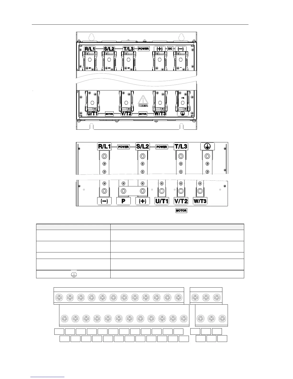
e: 110~315kW Main Circuit TerminalsSchematic
Fig.1-8 110~315kW Main Circuit TerminalsSchematic
f:355-400kW Main Circuit Terminals
Fig.1-9 355~400kW Main Circuit TerminalsSchematic
Table 1-2 main circuit terminal functions
AC power input terminals for connecting to 3-phase AC380V
power supply.
AC output terminals of inverter for connecting to 3-phase
induction motor.
Positive and negative terminals of internal DC bus.
Connecting terminals of braking resistor. One end connected
to + and the other to B.
2.3.2 Control circuit terminals
Fig. 1-10 control circuit terminalsschematic
DI1
+24V
DI2
PLC
DI3
COM
DI4
DI5
COM
DI6
Y1
Y2
+10V
R1A R1B
R1C
R2A R2B
R2C
AO1
AI1
GND
AI2
485+
AI3
485-
PE
DI7/HI
AO2
GND