119 PB
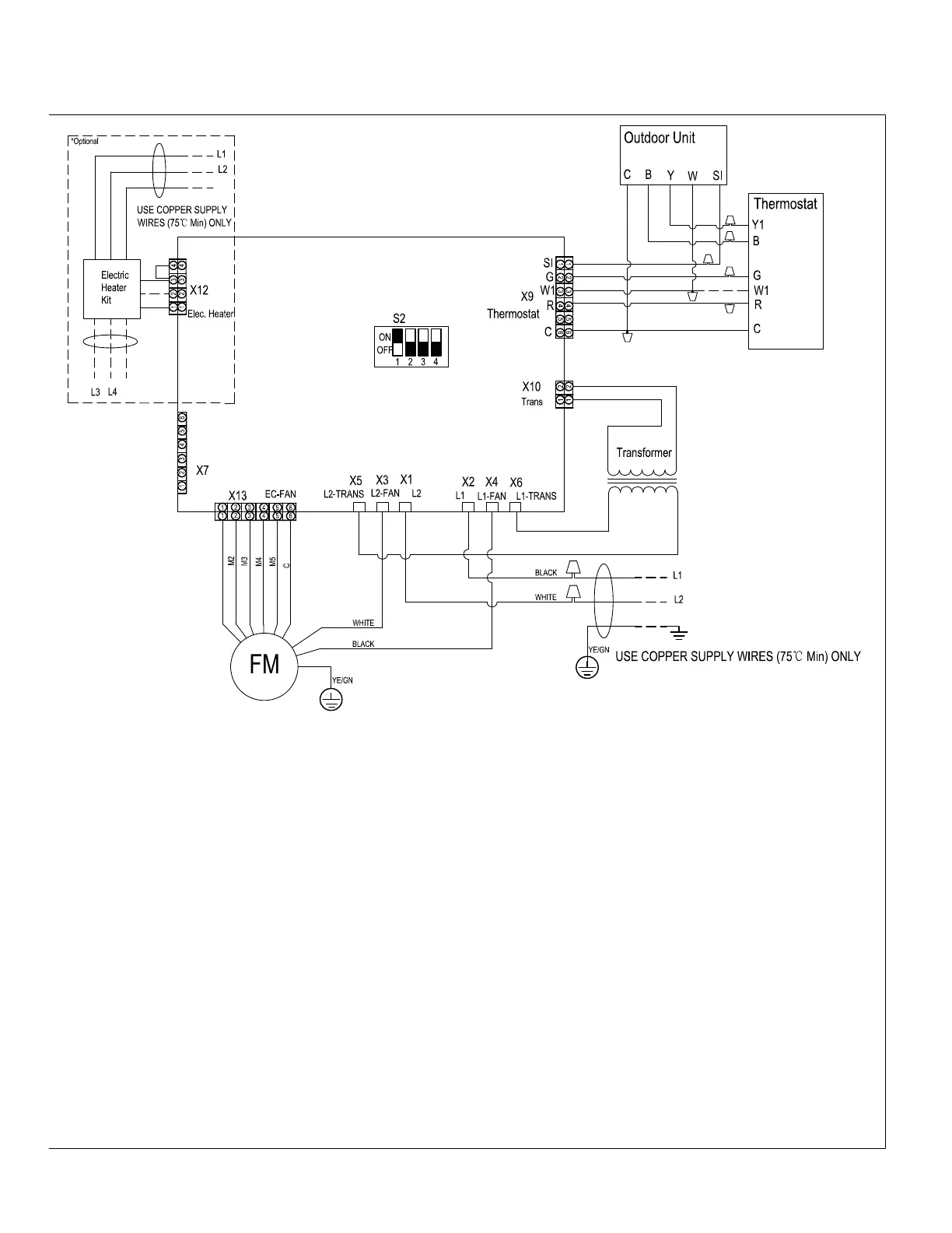
WIRING DIAGRAMS
Indoor Units
L1 and L2 connect to the
Electric Heater Kit if Installed
GND
GND
GND
Table for thermostat terminal callouts:
R - 24V
C - Common
G - Fan
Y - Call for cooling
B - Reversing Valve engage for Heating
W1 - Call for Aux/defrost heating.
SI - Signal between matched AHU/ODU
Note: Set thermostat to "B" on setup to engage Reversing valve for heating
Figure 801 (Indoor Units)
NOTES:
1. Use copper wire (167˚F Min) only between disconnect switch and unit.
2. Ensure all wiring complies National and local electrical codes.
3. If any of the original wire supplied must be replaces, use the same or equivalent type.,
4. Connect R to R, G to G, etc. See installation instruction for details
5. Check airflow table to ensure appropriate operations.
6. The Electric Heater Kit is optional. If the electric heater kit needs to be installed please see Installation manual for unit and
accessory kit for details.
7. The dashed line means that the component or wire is optional.
8. The DIP switch S2 in the diagram is the factory default configuration. In actual use, please set S2 to choose blower speed
according to the value of static pressure.
9. DO NOT connect wire (W1) from controller to indoor PCB, if there the electric heater kit is not installed.
 Loading...