46 PB
INSTALLATION
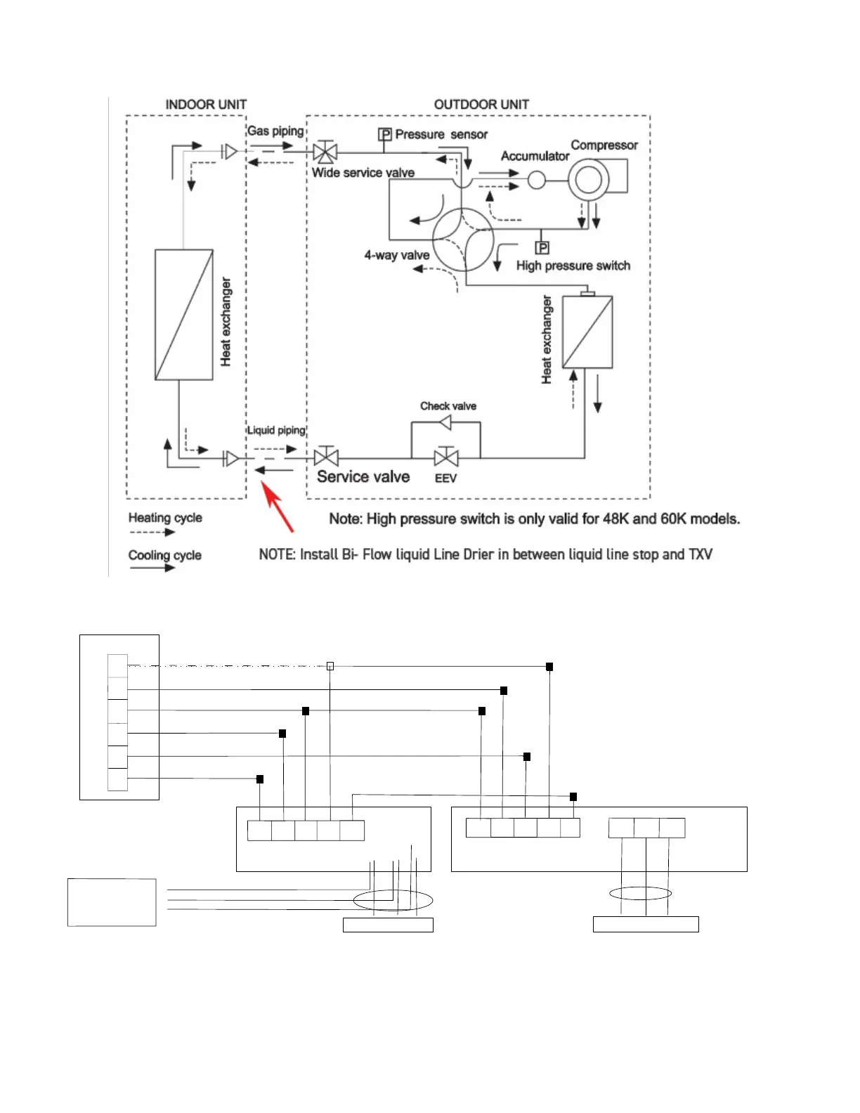
Refrigerant Flow Diagram
Figure 304
W1
B
C
R
Y
G
G
R
C
W1
SI
C
B
Y
W
SI
L1 L2
G
POWER SUPPLY
POWER SUPPLY
L1
L2
G
ELECTRIC
HEATER
KIT
L1
L2
G
Indoor Unit
Outdoor Unit
Power
Terminal
Panel
NOTE: WHEN OPTIONAL ELECTRIC
HEATER KIT IS INSTALLED, CONNECT
POWER TO THE INDOOR UNIT
TO THE LOAD SIDE OF THE ELECTRIC
HEATER KIT POWER SUPPLY
L1
L2
G
LINE
LOAD
TABLE FOR THERMOSTAT TERMINAL CALLOUTS:
R - 24V
C - COMMON
G - FAN
Y - CALL FOR COOLING
B - REVERSING VALVE ENGAGE FOR HEATING
W1 - CALL FOR AUX/DEFROST HEATING.
SI - SIGNAL BETWEEN MATCHED AHU/ODU
NOTE: SET THERMOSTAT TO "B" ON SETUP TO ENGAGE
REVERSING VALVE FOR HEATING
Diagram of refrigerant cycle & Wiring
Refrigerant flow diagram
Electrical wiring diagram - Example: Matched AHU+ODU
Note:
The SI (signal) wire between the indoor and outdoor units is not applicable when the outdoor unit is connected to an indoor unit of a
different brand. In a matched system, SI (signal) enables more energy-savings when the outdoor unit is connected to an indoor unit
of the same brand. SI (signal) is not required in non-matched configurations.
5
Figure 303
Electrical wiring diagram - Example: Matched AHU+ODU
The SI (signal wire) between indoor and outdoor units is not necessary when the outdoor unit is connected to the indoor unit of a different brand.
In a matched system the SI (signal) connection enables energy savings by matching low load demands.
 Loading...