49 PB
INSTALLATION
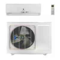
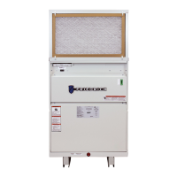
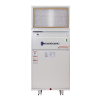
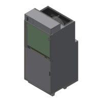
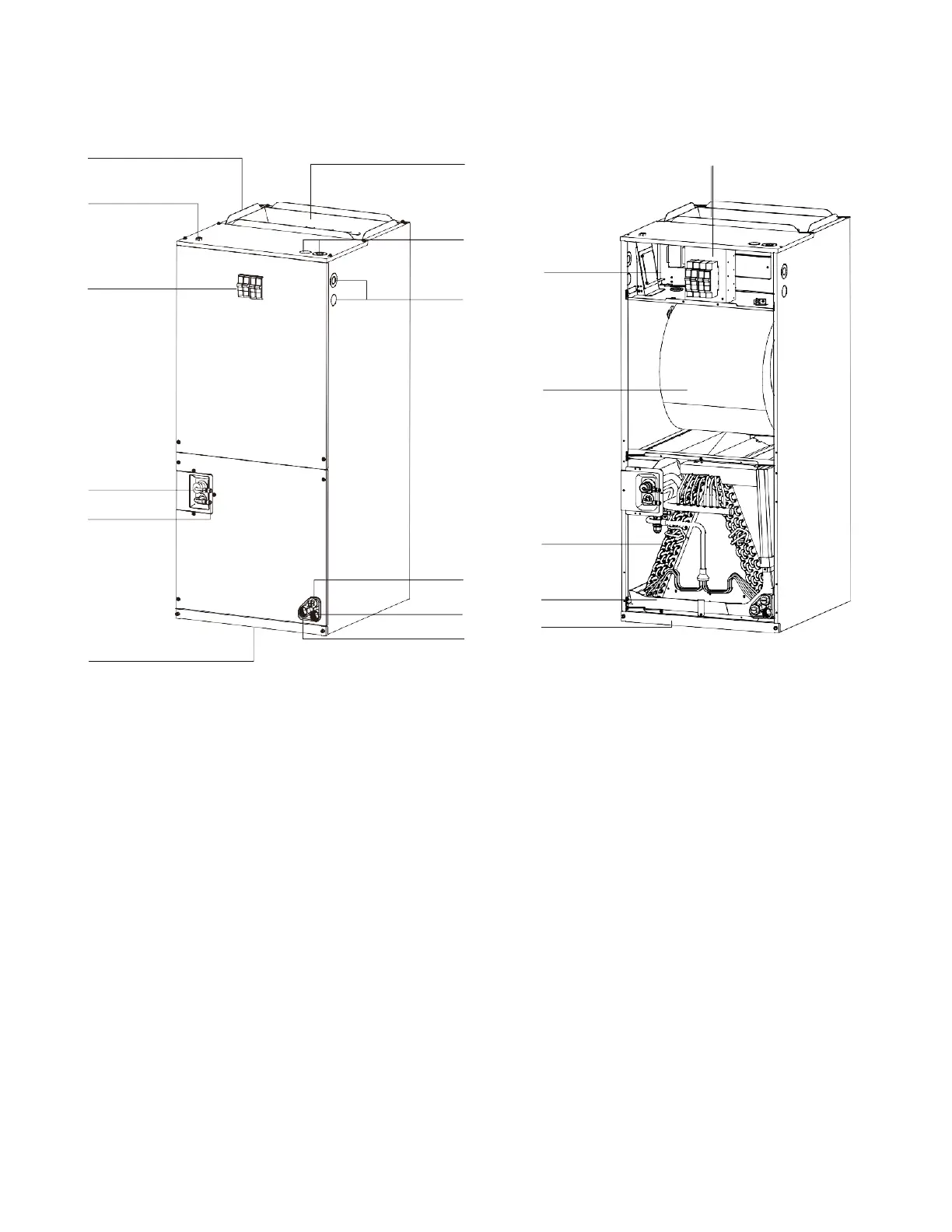
Indoor Unit - Component Identification
Composition of the Air Conditioner
8
13
14
15
16
17
18
NOTE: The figures are based on the external views of the standard model.
Shape and format may differ for the air conditioner model you have selected.
1. Supply air outlet flange
2. Low voltage connection (for 24V)
3. Circuit breaker switch (Optional)
4. Refrigerant pipe (Gas)
5. Refrigerant pipe (Liquid)
6. Return air inlet
7. Auxiliary drain connection
8. Primary drain connection
9. Auxiliary drain connection
10. Knockout for power cable
11. Knockouts
12. Supply air outlet
13. Auxiliary heater (Optional)
14. Electrical enclosure
15. Blower fan
16. Coil
17. Condensate drain pan
18. Filter cover
Indoor unit
Figure 305
 Loading...