60 PB
INSTALLATION
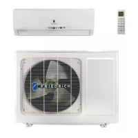
Outdoor Unit Handling and Installation location Selection
Note:
The SI (signal) wire between the indoor and outdoor units is not applicable when the outdoor unit is connected to an indoor unit of a
different brand. In a matched system, SI (signal) enables more energy-savings when the outdoor unit is connected to an indoor unit
of the same brand. SI (signal) is not required in non-matched configurations.
Installation instructions
Transportation and handling before installation
Transport the product as close to the installation location as practical
before unpacking.
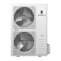
• Handling Method
When handling the unit, ensure the unit is balance, check that
connection is secure, then lift up smoothly.
(1) Do not remove any packing materials.
(2) Hang the packaged unit with two ropes, as shown in
Fig. below.
• Handling
Make sure the product is protected by package, cloth, or
similar when it is being moved.
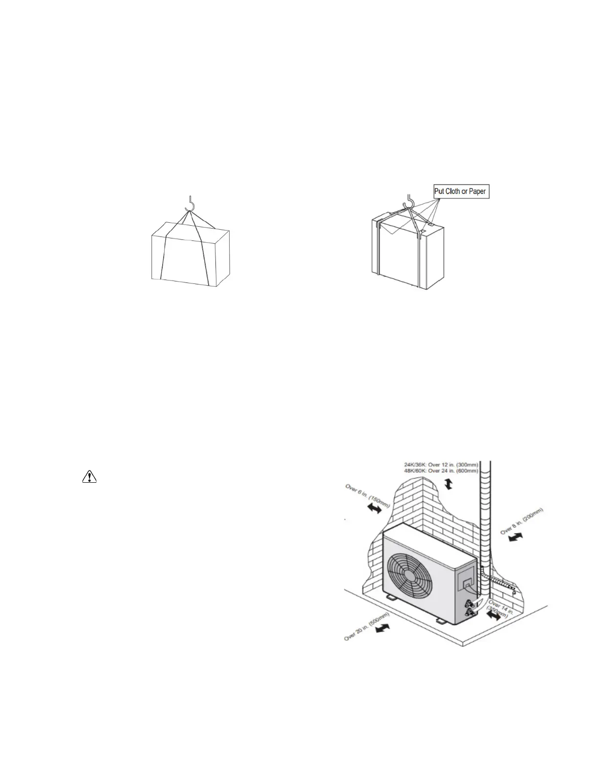
Installation locations selection
NOTE:
When operating the air conditioner in low outside temperature, be sure to follow the instruction described below.
• Never install the outdoor unit in a location where air inlet/outlet side may be exposed directly to wind.
• To prevent exposure to wind, install the outdoor unit with the air inlet side facing the wall.
• To prevent exposure to wind, it is recommended to install a (Field supplied) wind baffle on the air outlet side of the outdoor unit.
•
Bef
Wh
o
er
re
e it is
choosing the installation
ind gusts
si
.
te, obtain user's approval.
ect sunshine.
i
n
c
r
r
ho
t ai
ease of op
r.
eration sound or vibration.
TV set or radio To limit EMF exposure.
Avoid the fol
i
c
n
e
e/f
s fo
rye
r
r
inst
oil.
allation as lifecycle of product can be deteriorated.
os
er
i
low
e is mach
ing p
ve locations
la
- Increase
e
r
r
e t
e co
rr
h
rrosive gases may be present
d maintenance must be done.
ere there is high-frequency or wireless equipment.
• Whe
• Whe
r
r
n
e adequate ai
e it is not exposed to
ot exposed t
r flow i
o
s
r
dir
possi
ect
ain and
w
ble.
d
• Where neighbors are not disturbed by o
• Where rigid wall or support is availabl
i r
p
e to p
• Where there is no risk of combustible gas leakage
er
r
a
event th
.
tion sound o
e
• Where it is at least 10ft (3m) away from the antenna of
• Please install it in an area that are prone to snow above anticipated snow depth.
CAUTION
•
•
•
S
W
W
a
h
he
• Wh
lt co
Install drainage elbow and condensate drain hose
• Condensate may drain from the outdoor unit when the unit
operates in heating mode. It is recommended to install the
supplied elbow to allow installer to direct drainage away from
the unit.
• Connect the condensate drain hose [field-supplied, inside
diameter: 3/5" (15mm) ] as shown in the figure for drainage.
(1) Use washers when mounting the unit with bolts to the foundation.
(2) When fastening the outdoor unit with bolts. Reference Fig 1. for fastener hole locations.
(3) Fasten the outdoor unit as shown in Fig 2.
(4) Make sure to fasten the outdoor unit tight and horizontal to ensure the unit operates correctly.
(5) Make sure the condensate drain is routed away to ensure safe and reliable operation.
(6) Use a robust base for the equipment (made of concrete, etc.) The equipment should be installed no less than 4" (10
cm) above grade level, to ensure proper drainage and operation. Failing to meet the installation requirements may
reduce equipment life cycle. (Fig.3)
6
 Loading...