57 PB
INSTALLATION
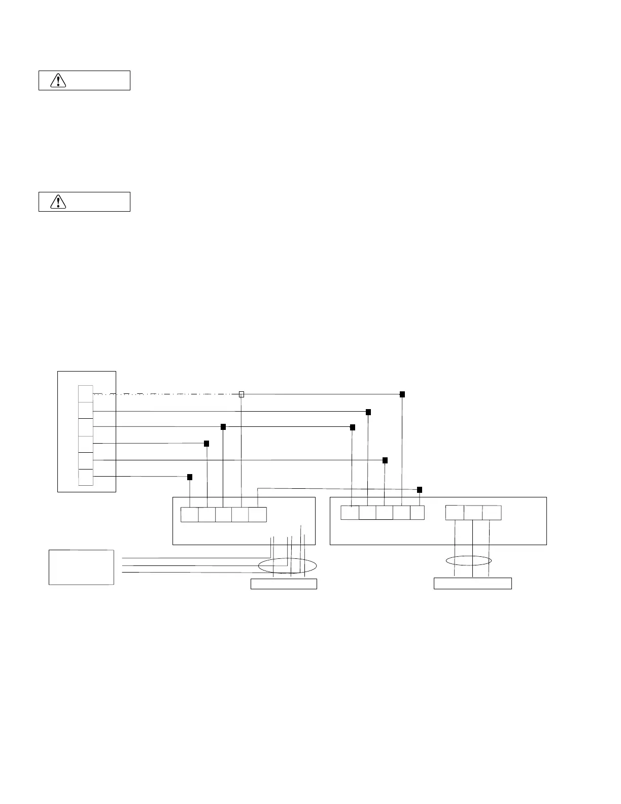
Indoor Unit - Electrical Wiring
W1
B
C
R
Y
G
G
R
C
W1
SI
C
B
Y
W
SI
L1 L2
G
POWER SUPPLY
POWER SUPPLY
L1
L2
G
ELECTRIC
HEATER
KIT
L1
L2
G
Indoor Unit
Outdoor Unit
Power
Terminal
Panel
NOTE: WHEN OPTIONAL ELECTRIC
HEATER KIT IS INSTALLED, CONNECT
POWER TO THE INDOOR UNIT
TO THE LOAD SIDE OF THE ELECTRIC
HEATER KIT POWER SUPPLY
L1
L2
G
LINE
LOAD
TABLE FOR THERMOSTAT TERMINAL CALLOUTS:
R - 24V
C - COMMON
G - FAN
Y - CALL FOR COOLING
B - REVERSING VALVE ENGAGE FOR HEATING
W1 - CALL FOR AUX/DEFROST HEATING.
SI - SIGNAL BETWEEN MATCHED AHU/ODU
NOTE: SET THERMOSTAT TO "B" ON SETUP TO ENGAGE
REVERSING VALVE FOR HEATING
5. Electical Wiring
5.1 Electrical Installation
• Before proceeding with electrical connections, make certain the power supply matches the informa-
tion on the unit rating label. See unit wiring label for proper high and low-voltage wiring. Make all electrical
connections in accordance with the NEC and any local codes or ordinances that may apply. Refer to the
NEC(USA) or CSA (Canada) for wire sizing. Use copper wire only.
• Every installation must include an NEC(USA) or CSA (Canada) approved over-current protection
device.
Disconnect all power before servicing or installing this unit.
To avoid electrical shock, please ensure the air conditioner is properly grounded.
All routing of electrical wiring must be made through provided electrical knockouts. Do not cut, puncture or
alter the cabinet provided for electrical wiring.
Knockouts are provide on the indoor unit top panel and sides of the cabinet to allow for the entry of the power
supply cable conductors. If the knockouts on the cabinet sides are used for electrical conduit, an adapter ring
must be used in order to meet UL 1995 safety requirements. An MEC or CEC approved strain relief is to be
used at this entry point. Some codes/municipalities require the supply wire to be enclosed in conduit. Consult
your local codes.
Wiring diagram - Matched AHU+ODU
NOTE:
(1) Do not connect dashed line when electric heater is not used.
(2) Wiring must be performed according to wiring diagram that pasted on indoor unit.
(3) The SI wire that connects between the matched indoor and outdoor units improves the efficiency of the
unit, allowing it run a slower speeds in low demand. In non matched applications the unit will run without
error, even though the SI cable is not connected.
(4) Since the thermostat is locally provided, the terminal block in the diagram may differ from the actual one.
The letter Y is the same as Y1.
Electrical data
Max. Running Current (A): REFER TO NAMEPLATE
CAUTION
WARNING
24K/36K 208/230V ~/60Hz 15 30
See NEC
5×18AWG
48K/60K 208/230V ~/60Hz 15 30
See NEC
5×18AWG
Model
(Capacity)
Power Supply
ELB
Rated Current
(A)
Nominal Sensitive
Current (B)
Power Source
Cable Size
Transmitting
Cable Size
Thermostat
Signal Size
13
Figure 306
 Loading...