58 PB
NOTE:
(1) Follow National and local codes and regulations when sizing conductors. Minimum wire sizes are
stated above.
(2) When transmitting cable length is longer than 262ft. (80m), a larger wire size should be selected.
(3) Install main switch and ELB for indoor and outdoor unit separately. Select the high response type
ELB that is acted within 0.1second.
(4) If auxiliary heater is required and already installed on indoor unit, power source cable should be
installed separately and the size should be selected in accordance National and Local Electrical
Codes.
5.2 Change of Static Pressure
The static pressure can be selected by changing Dip Switches on electric board.
Static Pressure Setting:
Dip Switch S2
Setting
Blower Speed Tap Fan Speed Select
Static Pressure
(W.C.[kPa]) 24K
Static Pressure
(W.C.[kPa]) 36K
Static Pressure
(W.C.[kPa]) 48K/60K
2
3
4
5
Medium Low
(Default setting)
Medium
Medium High
High
0.18[0.045]
0.25[0.08]
0.58[0.145]
0.8[0.2]
0.24[0.057]
0.4[0.1]
0.58[0.145]
0.8[0.2]
0.28[0.07]
0.4[0.1]
0.58[0.145]
0.8[0.2]
Note: Symbol “ ” indicates the position of the dip switch.
Symbol “ ” indicates any position of ON or OFF.
14
INSTALLATION
Indoor Units ‑ Electrical Wiring
Refer to Figure 203 Electric Heater Kit Selection Table for Specifications.
(5) When the Electric Heater Kit is used jumpers will need to be installed from L1 and L2 of the Indoor PCB to the breaker of L1 and L2 of the electric
heater kit.
5. Electical Wiring
5.1 Electrical Installation
• Before proceeding with electrical connections, make certain the power supply matches the informa-
tion on the unit rating label. See unit wiring label for proper high and low-voltage wiring. Make all electrical
connections in accordance with the NEC and any local codes or ordinances that may apply. Refer to the
NEC(USA) or CSA (Canada) for wire sizing. Use copper wire only.
• Every installation must include an NEC(USA) or CSA (Canada) approved over-current protection
device.
Disconnect all power before servicing or installing this unit.
To avoid electrical shock, please ensure the air conditioner is properly grounded.
All routing of electrical wiring must be made through provided electrical knockouts. Do not cut, puncture or
alter the cabinet provided for electrical wiring.
Knockouts are provide on the indoor unit top panel and sides of the cabinet to allow for the entry of the power
supply cable conductors. If the knockouts on the cabinet sides are used for electrical conduit, an adapter ring
must be used in order to meet UL 1995 safety requirements. An MEC or CEC approved strain relief is to be
used at this entry point. Some codes/municipalities require the supply wire to be enclosed in conduit. Consult
your local codes.
Wiring diagram - Matched AHU+ODU
NOTE:
(1) Do not connect dashed line when electric heater is not used.
(2) Wiring must be performed according to wiring diagram that pasted on indoor unit.
(3) The SI wire that connects between the matched indoor and outdoor units improves the efficiency of the
unit, allowing it run a slower speeds in low demand. In non matched applications the unit will run without
error, even though the SI cable is not connected.
(4) Since the thermostat is locally provided, the terminal block in the diagram may differ from the actual one.
The letter Y is the same as Y1.
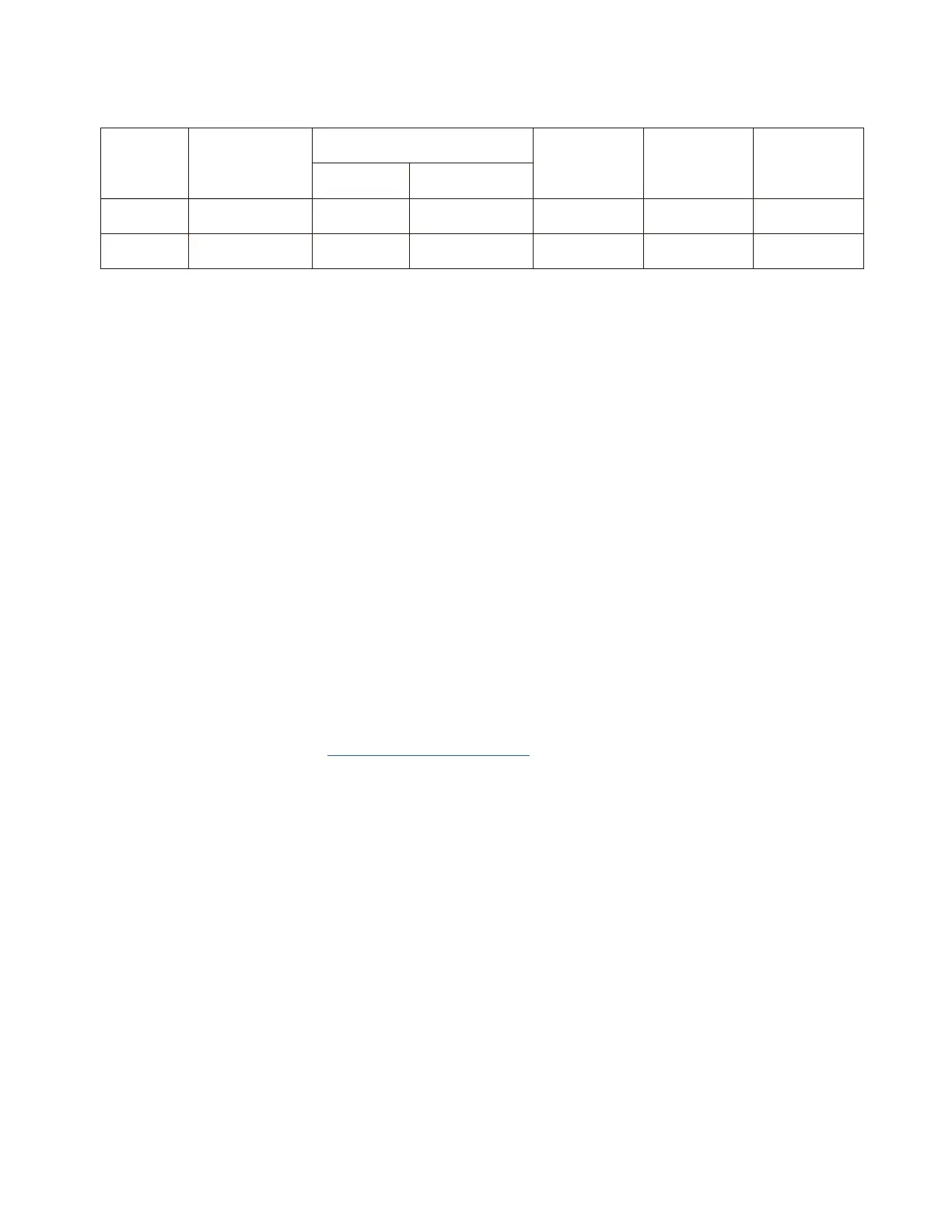
Electrical data
Max. Running Current (A): REFER TO NAMEPLATE
24K/36K 208/230V ~/60Hz 15 30
See NEC
5×18AWG
48K/60K 208/230V ~/60Hz 15 30
See NEC
5×18AWG
Model
(Capacity)
Power Supply
ELB
Rated Current
(A)
Nominal Sensitive
Current (B)
Power Source
Cable Size
Transmitting
Cable Size
Thermostat
Signal Size
 Loading...