14 PB
SPECIFICATIONS
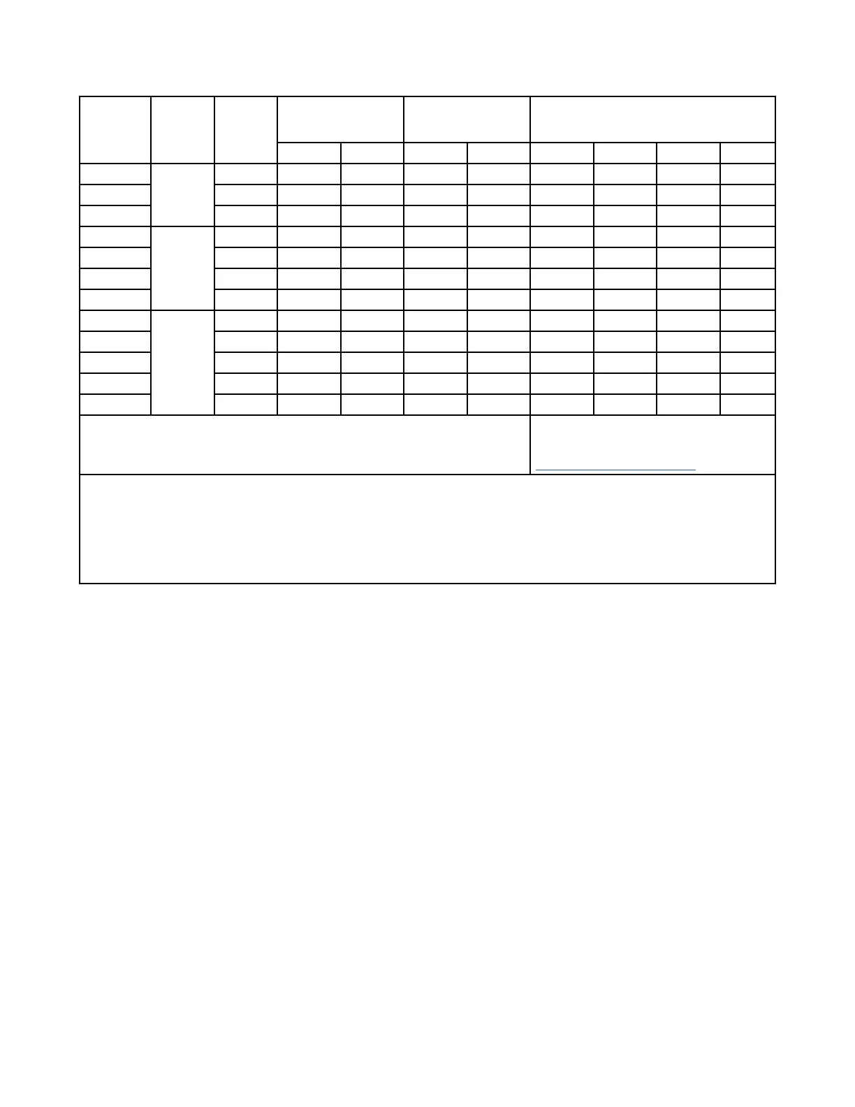
Electric Heater Kit Selection Table
Figure 203
Electric
Heat Kit
Model
Air
Handler
Model
Electric
Heat (kW)
MIN. Circuit Ampacity MAX. Fuse or
Breaker (HACR)
Ampacity
Fan Speed Tap
230VAC 208VAC 230VAC 208VAC 2 3 4 5
AUX5KW 24k 5 28.3 25.9 30 30 O O O O
AUX7KW 7.5 40.7 37.2 45 40 X O O O
AUX10KW 10 53.2 48.5 60 50 X X O O
AUX5KW 36k 5 29.8 27.4 30 30 O O O O
AUX7KW 7.5 42.2 38.7 45 50 X O O O
AUX10KW 10 54.7 49.9 60 50 X X O O
AUX15KW 15 42.2+36.9 38.6+33.8 45+40 40+35 X X X 0
AUX5KW 48K/60K 5 31.8 29.4 35 30 0 O O O
AUX7KW 7.5 44.8 40.7 45 45 X O O O
AUX10KW 10 56.7 51.9 60 55 X X O O
AUX15KW 15 44.8+36.9 40.7+33.8 50+40 50+35 X X O O
AUX20KW 20 56.7+49.9 51.9+45.2 60+50 60+50 X X X O
O = Fan Speed tap may be used
X= Fan speed tap may not be used
See Blower Data(Indoor Units)
NOTES:
• When optional electric heater kit is installed, obtain power for AHU from load side of L1 and L2 of electric heater kit.
• It is recommended that the electric heater kit should be installed in cold climate regions or when long piping is used.
• Properly size the auxiliary heater per the table above.
• Ampacities for MCA and Fuse/breaker include the blower motor.
• Heat pump systems require a specified airflow. Each ton of cooling requires between 350 and 450 cubic feet of air per minute
(CFM).
 Loading...