63 PB
INSTALLATION
Outdoor Unit ‑ Wiring
• Follow safe procedures to shut off the breaker of the outdoor/indoor unit prior to performing any and all
electrical work. For the outdoor unit please allow 3 minutes before working on the electrical, as the inverter
boards capacitor must discharge. (Risk of personal injury can occur if not followed)
• Make sure that the indoor and outdoor fans have stopped completely before performing electrical work or
reaching into the equipment.
• Protect the wires, electrical parts, etc. from small animals as well as lizards and ants. If not protected,
damage to the electrical system or fire could occur.
• Prevent the wiring from touching refrigerant pipes, plate edges, and electrical parts inside the unit.
• Install an ELB (Electric Leakage Breaker) at the power source. If ELB is not used, it can cause electric shock
or fire.
• This unit utilizes an inverter, which means that protections must be made to ensure harmonics in the electri-
cal system are maintained, as well it is recommended that a surge protector be installed inline to protect the
electrical components.
• The use of temporary connection wires, stranded wires, extension cables or control line connections, is
prohibited. The use of such connections may cause electric shock or fire.
The tightening torque of each screw shall be as followed.
M4: 0.7 to 1.0 ft.lb (1.0 to 1.3 N·m)
M5: 1.5 to 1.8 ft.lb (2.0 to 2.5 N·m)
M6: 3.0 to 3.7 ft.lb (4.0 to 5.0 N·m)
M8: 6.6 to 8.1 ft.lb (9.0 to 11.0 N·m)
M10: 13.3 to 217 ft.lb (18.0 to 23.0 N·m)
Proper torquing of fasteners ensures not only safe and reliable operation but lower risk of ARC or fire.
Wire connection steps:
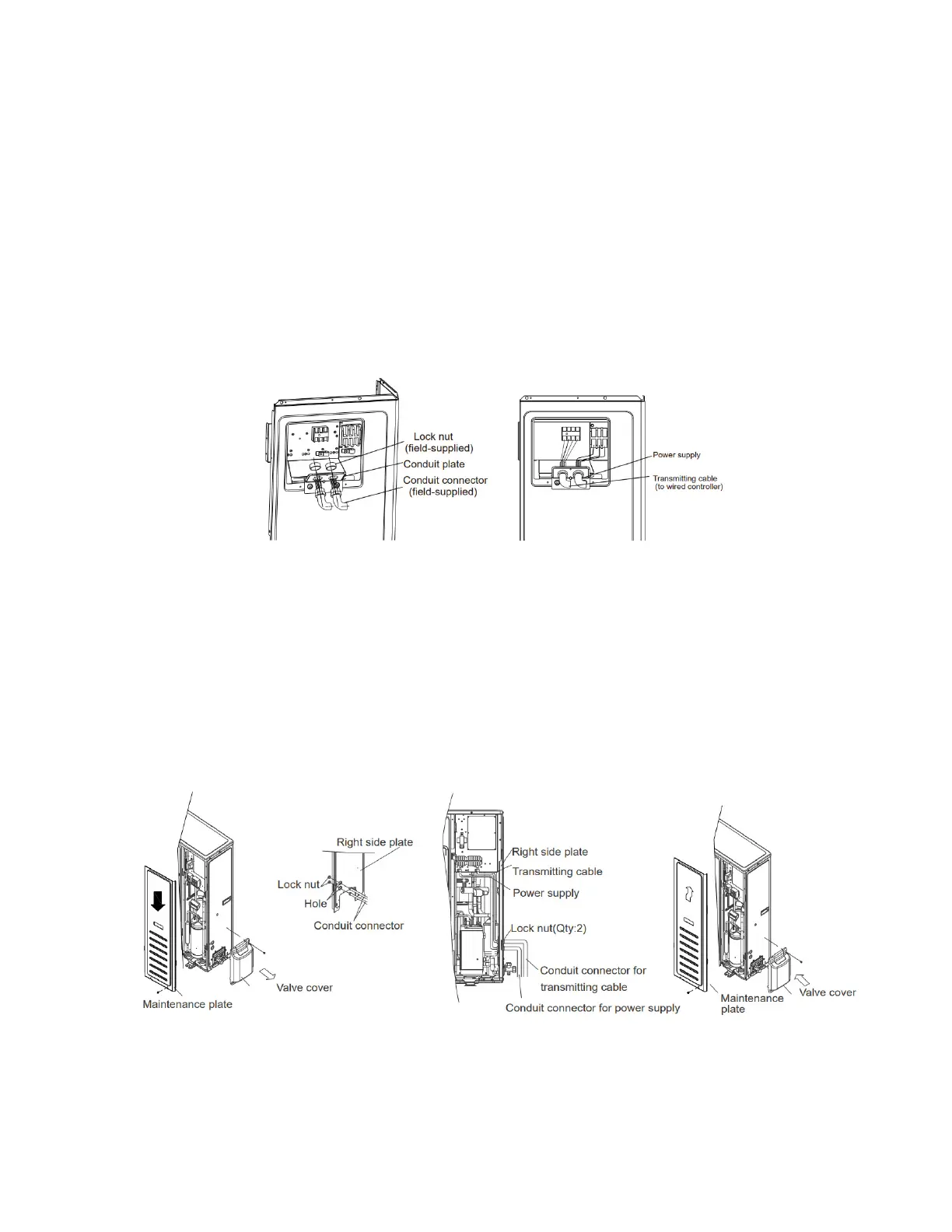
24K/36K
• Electric box cover removal- Unscrew the mounting screws to remove the electric box cover.
• Fasten the power supply cable and the transmission cable to the conduit holder using a lock nut.
• Connect the power supply cable and the transmission cable to terminal.
• Fasten the power supply cable and the transmission cable with the cable clamp.
• Seal holes and gaps using putty.
• Place cables side by side. (Do not overlap the cables.)
• Re-install the electric box cover back after completion of the work.
48K/60K
• Electric box cover removal- Unscrew the mounting screws, valve box and maintenance panel to remove the
electric box cover.
• Fasten the power supply cable and the transmission cable to the conduit holder using a lock nut.
• Connect the power supply cable and the transmission cable to terminal.
• Fasten the power supply cable and the transmission cable with the cable clamp.
• Seal holes and gaps using putty.
• Place cables side by side. (Do not overlap the cables.)
• Re-install the electric box cover back after completion of the work.
 Loading...