66 PB
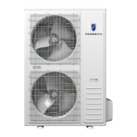
Precautions and steps during brazing service valve:
a. Remove the caps from both the liquid and gas service valve
service ports at the outdoor unit.
b. Braze the liquid piping and gas piping to the respective valve at
the outdoor unit.
Prior to brazing, wrap a wet cloth around each service valve to
prevent heat damage while brazing.
A fire plate or divider can be used to protect painted surfaces and
insulation while brazing.
c. Cool joints and other heat sensitive components with a wet rag
during brazing.
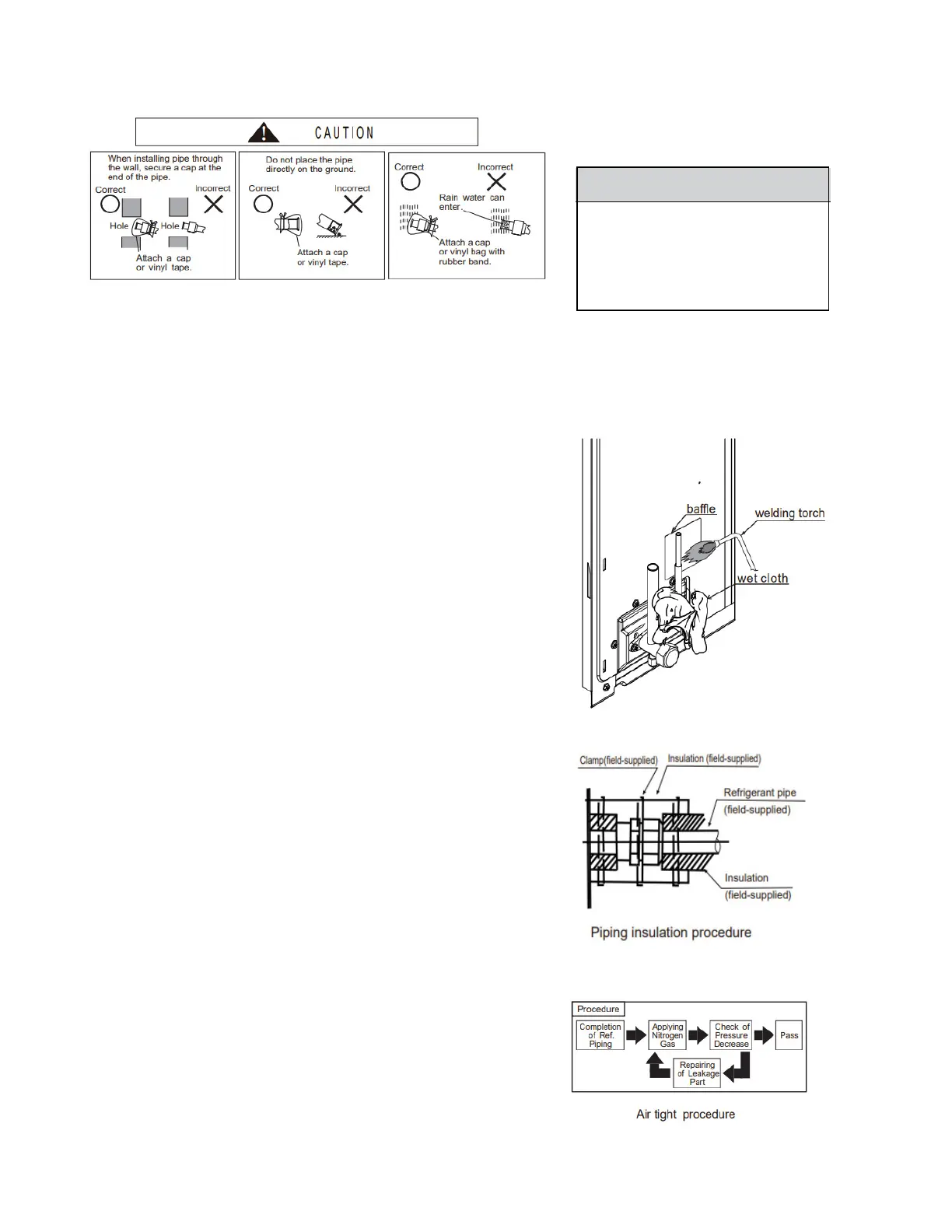
(3) After connecting the refrigerant pipes, insulate the pipes according
to local codes and temperature/humidity conditions. See also
detailed figure.
·For outdoor unit side, insulate all piping including valves.
·Cover piping joints with pipe cover.
·Using piping tape, apply taping starting from the entry of outdoor unit.
- Secure the end of the piping tape with adhesive tape.
- When piping has to be routed above ceiling, closet or area where
temperature and humidity are high, apply additional insulation
for prevention of condensation.
5. Air tight test
Use Nitrogen only.
Using charging hose, connect the gauge manifold at the nitrogen
cylinder to the check joints of the liquid line and the gas line stop-valves.
Perform the air-tight test.
Don't open the gas line stop valves.
Apply nitrogen gas pressure of 550 psig (3.8 MPa).
Check for any gas leaks at the flare nut connections, or brazed
parts utilizing gas leak detector or foaming agent.
In addition, observe the gas pressure during the leak test to make sure that it does not decrease.
After the air tight test, release nitrogen gas.
4
(1)
. Piping connection
(2)
Con
Conne
firm
ct t
tha
he
t
the
indoor
val
v
uni
es
t
are
and
c
t
lo
he
s
ed.
refrigerant pipes. The refrigerant pip it
pp
h
l
a
ie
d
phosphorous-copper alloy material s
ou
ing
uc
t
h
s
door
as
hould
S
uni
ilf
t
be
wi
os-15
th
bra
f
z
or
ield-s
ed
equ
w
u
ivalen t.
3
(1)
.
P
Refr
ipe
ig
cu
era
tt
nt
ing
-
piping work
Cut the copper pipe correctly with pipe cutter.
(2) Burrs removal-
Completely remove all
he c
burr
opper
s f
rom
pipe
the
cut
downward
cross
t
se
o
ct
pre
ion
ve*Position the end of t
o
n
t
b rr
p
s f
pe
ro
. f
t
h
u
e i
m dropping in the pipe.
INSTALLATION
Refrigerant Piping
NOTICE
A Bi -Flowliquid line drier is required
to be installed on the refrigerant
system during installation or any
refrigerant system repairs. Install in
between liquid line stop and TXV.
 Loading...