79 PB
OPERATION
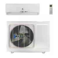
Outdoor Unit Field Settings
Step 3:
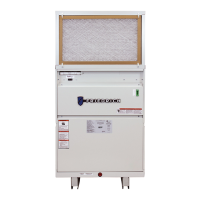
Open the maintenance panel.
Step 4:
Change the DIP switch position (referring to outdoor wiring diagram ) ON position on the main
control board.
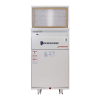
Step 5:
Apply power to the unit via the electrical disconnect
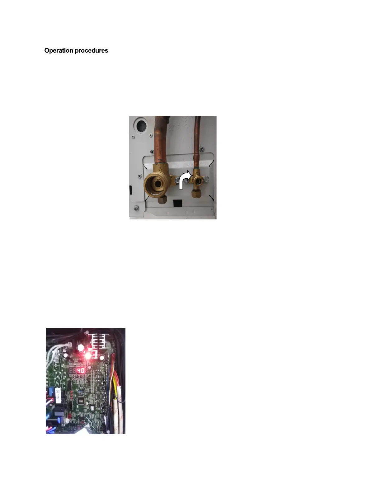
Step 6:
Check if “40” is displayed on the 7 segment display of the main control board.
(48K/60K):
Step 1:
Remove power from unit via electrical disconnect
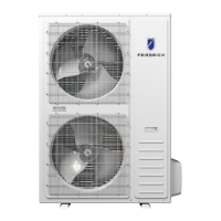
Step 2:
Close the stop valve of the liquid
piping
with an Allen wrench in a clockwise direction.
 Loading...