1.12 Assemble Power Supply Cord to Charging Board
Before securing the power cord to the Charging Station, carefully lay the length of the cord out,
beginning from the Charging Station and leading to the main power supply to insure that the
Charging Station is placed close enough to the main power for the supply cord to reach.
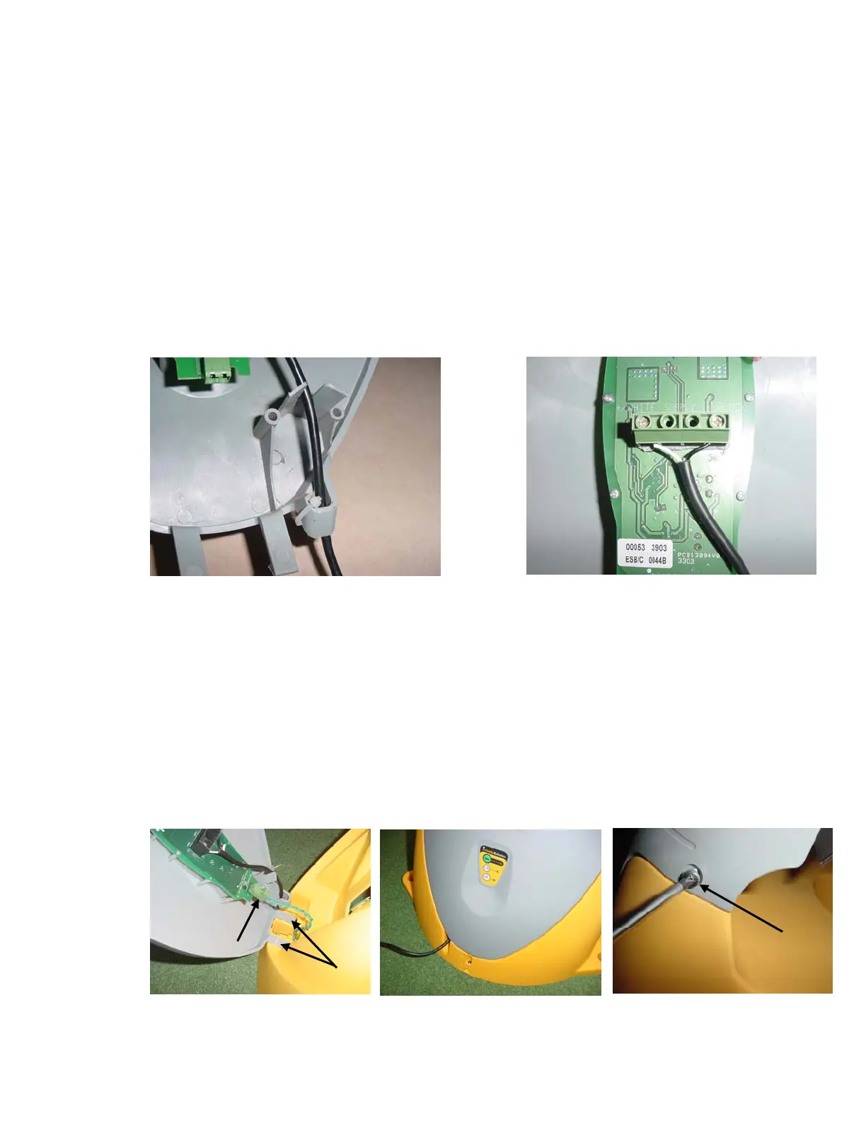
Route the power supply cord into the Charging Station cover as shown in Figure 1.18, with the
white lead positioned at the LH screw and the black lead positioned at the RH screw. Place each
wire under its’ respective screw and tighten firmly with a small screwdriver. See Figure 1.19.
Lastly, place the provided nylon wire tie through the holes in the power cord-retaining slot and
tighten snugly. See Figure 1.18.
The power supply for the Charging Station must be attached to the Charging Station cover at the
control board prior to assembling the cover to the base. Refer to Figure 1.1 for base and cover
identification. Located on the back of the cover you will find the operating control board and the
two screw connectors for attaching the power supply cord. The power supply cord has two leads,
white and black. It is required that the white lead be located on the LH screw (when viewing the
board) and the black wire attached to the RH screw. As a guide, the board is marked Black and
White above its’ respective screw. See Figure 1.19.
1.13 Charging Station Assembly
+/WHITE SUPPLY -/BLAC
Figure 1.18
Routing the Power Supply cord into the cover
Figure 1.19
Power Supply Cord Track through the cover
Align the two tabs on the lower section of the cover with the mated openings in the front lower
section of the base, see Figure 1.20. Carefully push the tabs of the cover into the openings in the
base as shown. While in the position pictured, attach the perimeter wire connector to the
Perimeter Switch board as shown.
Pivot the cover towards the base and confirm proper way out of the power supply cable from the
notch in the base, as shown in Figure 1.21.
Insert the two screws provided on both sides of the top section of the cover. Lightly tighten with a
Phillips screwdriver. See figure 1.22.
Figure 1.20 –
Cover and Base Assembly
Cover tabs
Perimeter wire
connector
Figure 1.21 –
Proper position of the
Power Supply cable
Screws –
Base
Cove
Figure 1.22 –
Cover and Base Assembly
22