5
Follow the installation wizard in the individual sections and complete the in-
stallation.
6
Add system components in Solar.web and start up the PV system.
The network wizard and the product setup can be carried out independently of
each other. A network connection is required for the Solar.web installation wiz-
ard.
Ethernet:
1
open access point
192.168.250.180
2
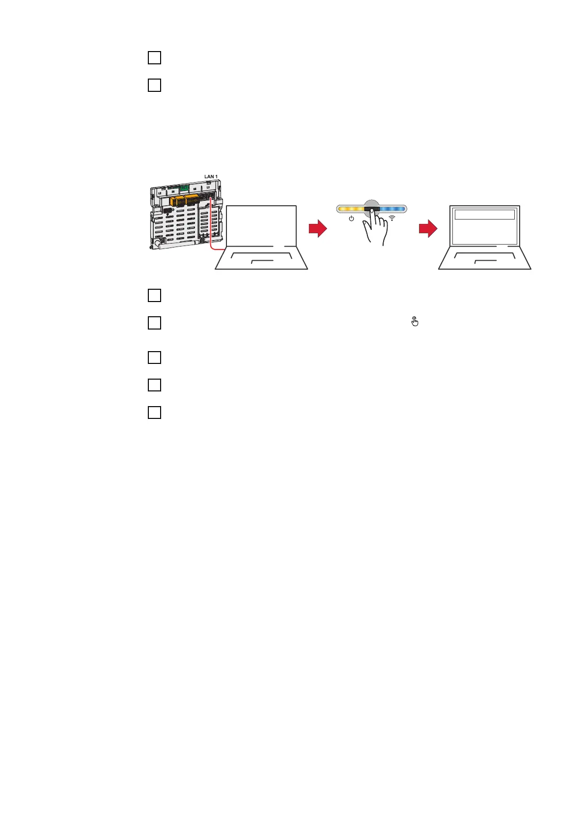
1
Establish a connection to the inverter (LAN1) with a network cable (CAT5
STP or higher).
2
Open the access point by touching the sensor once
ü
Communication LED flashes blue.
3
In the browser address bar, enter and confirm IP address 169.254.0.180. The
installation wizard is opened.
4
Follow the installation wizard in the individual sections and complete the in-
stallation.
5
Add system components in Solar.web and start up the PV system.
The network wizard and the product setup can be carried out independently of
each other. A network connection is required for the Solar.web installation wiz-
ard.
103

 Loading...


