EasyManuals Logo

Fronius Primo GEN24 Series User Manual

Fronius Primo GEN24 Series
232 pages
To Next Page IconTo Next Page
To Previous Page IconTo Previous Page
Page #22 background imageLoading...
Page #22 background image
+
-
00
1
6
7
1
Energy flow dir-
ection of the in-
verter
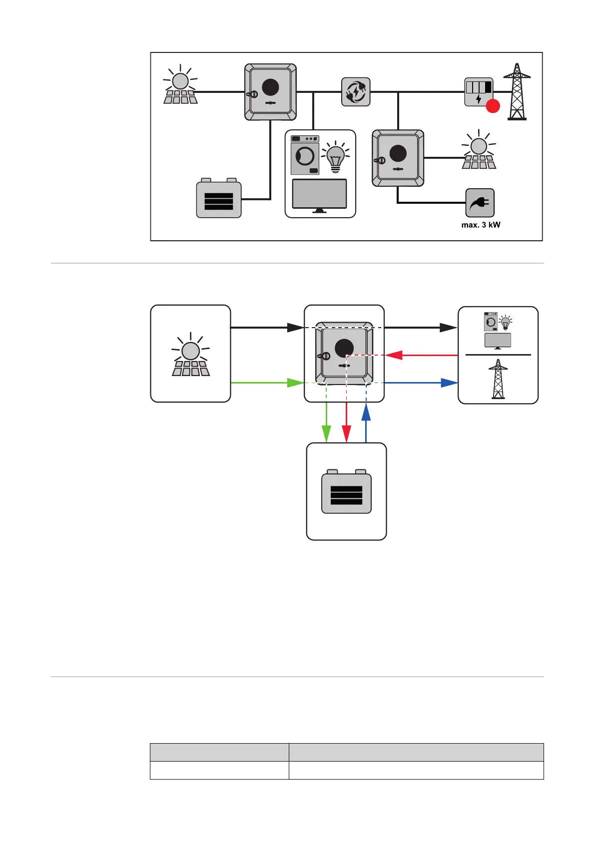
In the case of hybrid inverters, there are four different energy flow directions:
AC~DC=
DC=
(1)
(2)
(4)
(3)
+
-
(1) PV module – inverter – load/grid
(2) PV module – inverter – battery*
(3) Battery – inverter – load/grid*
(4) Grid – inverter – battery*
* depending on the settings and local standards and regulations.
Operating states
(only for systems
with a battery)
Battery systems distinguish different operating states. In this case, the relevant
current operating state is displayed on the user interface of the inverter or in
Solar.web.
Operating state Description
Normal operation Energy is stored or drawn, as required.
22

Table of Contents

Other manuals for Fronius Primo GEN24 Series

Questions and Answers:

Question and Answer IconNeed help?

Do you have a question about the Fronius Primo GEN24 Series and is the answer not in the manual?

Fronius Primo GEN24 Series Specifications

General IconGeneral
TypeHybrid Inverter
THD< 3 %
Number of MPP trackers2
Max. efficiency98.1 %
Protection classIP66
DC isolationYes
AC Output Power3.0 kW to 10.0 kW
Max. apparent AC power3.0 kVA to 10.0 kVA
Max. output current (at grid voltage)13.0 A to 43.5 A
AC nominal voltage230 V
Number of DC connections2
Operating Temperature Range-25°C to +60°C

Related product manuals