WARNING!
Danger due to damaged and/or contaminated terminals.
This can result in serious injury and damage to property.
▶
Before making any connections, check the terminals for damage and con-
tamination.
▶
Remove contamination in the de-energized state.
▶
Have defective terminals repaired by an authorised specialist.
Module array -
general informa-
tion
2 independent PV inputs (PV 1 and PV 2) are available. These can be connected
to a different number of modules.
When using for the first time, set up the module array according to the respect-
ive configuration (also possible later in the “System configuration” menu under
the “Components” menu item).
Module array
configuration
3 ‑ 6 kW
IMPORTANT!
The installation must be carried out in accordance with the nationally applicable
standards and directives. If the Arc Fault Circuit Interrupter integrated in the in-
verter is used for the requirement according to IEC 63027 for arc detection, the
solar module strings must not be combined upstream of the inverter.
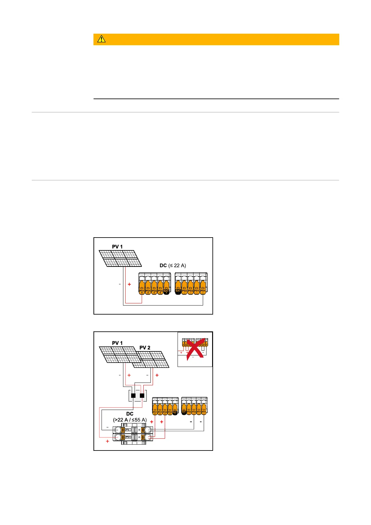
Current equal to or less than 22 A (I
dcmax
).
Module array settings:
PV 1: ON
PV 2: OFF
Combined solar module strings with total cur-
rent greater than 22 A (l
dcmax
).
Module array settings:
PV 1: ON
PV 2: OFF
PV 1 + PV 2 (connected in parallel):
ON
IMPORTANT!
The maximum current load of a single
terminal is 22 A. PV‑connection strings
with a total current of more than 22 A
must be split between both PV inputs
upstream of the terminals (I
SC max
≤ 55 A). The plug connection for split-
ting the total current must be suffi-
ciently dimensioned, suitable and cor-
rectly installed. Splitting the current
by bridging from PV 1 to PV 2 at the
terminal is not permitted.
75

 Loading...


