Optical sensor
To operate the inverter. See chapter
Button functions and LED status in-
dicator on page 35.
Communication LED
Indicates the inverter connection
status.
LAN 1 Ethernet connection for data commu-
nication (e.g. WLAN router, home net-
work or for commissioning with a
laptop see chapter Installation using
the web browser on page 102).
LAN 2 Reserved for future functions. Only
use LAN 1 to avoid malfunctions.
I/Os terminal Push-in terminal for digital inputs/
outputs. See chapter Permissible
cables for the data communication
connection on page 68.
The designations (RG0, CL0, 1/5, 2/6,
3/7, 4/8) on the terminal refer to the
Demand Response Mode function, see
chapter Functions andI/Os on page
109.
WSD terminal Push-in terminal for the WSD installa-
tion. See chapter "WSD (wired shut-
down)" on page 30.
Modbus terminal Push-in terminal for the installation of
Modbus 0, Modbus 1, 12 V and GND
(ground).
The data connection to the connected
components is established via the
Modbus terminal. The inputs M0 and
M1 can be selected for this purpose.
Max. 4 Modbus participants per input,
see chapter Modbus participants on
page 95.
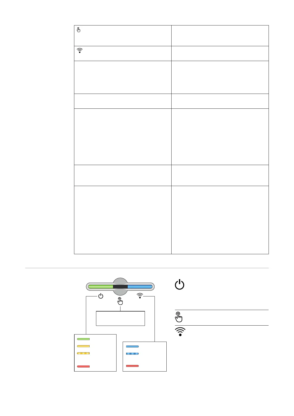
Button functions
and LED status
indicator
Ok
Standby
Uncritical Error
(flashing)
Critical Error
Network Error
Connecting
(flashing)
Connected
1x WLAN access point
2x WPS
3-6 sec. Quit Service Message
The status of the inverter is
shown via the operating status
LED. In the event of faults,
carry out the individual steps
in the Fronius Solar.start app.
The optical sensor is actuated
by touching with a finger.
The status of the connection is
shown via the communication
LED. To establish the connec-
tion, carry out the individual
steps in the Fronius Solar.start
app.
35

 Loading...


