EasyManuals Logo

Fronius Primo GEN24 Series User Manual

Fronius Primo GEN24 Series
232 pages
To Next Page IconTo Next Page
To Previous Page IconTo Previous Page
Page #159 background imageLoading...
Page #159 background image
10
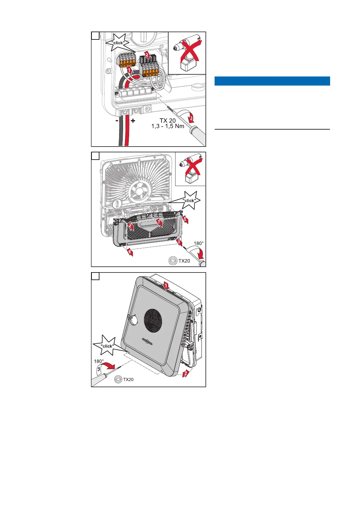
Insert the DC terminals into the re-
spective slot until they engage. Fasten
the screws of the strain-relief device to
the housing using a screwdriver (TX20)
and a torque of 1.3 – 1.5 Nm.
NOTE!
Risk due to overtorque at the strain-
relief device.
This may result in damage to the
strain-relief device.
Do not use a drill driver.
11
Place the cover on the connection
area. Tighten the 5 screws by rotating
them 180° to the right in the indicated
order using a screwdriver (TX20).
12
Clip the housing cover onto the invert-
er from above.
Press on the lower part of the housing
cover and tighten the 2 screws by ro-
tating them 180° to the right using a
screwdriver (TX20).
159

Table of Contents

Other manuals for Fronius Primo GEN24 Series

Questions and Answers:

Question and Answer IconNeed help?

Do you have a question about the Fronius Primo GEN24 Series and is the answer not in the manual?

Fronius Primo GEN24 Series Specifications

General IconGeneral
TypeHybrid Inverter
THD< 3 %
Number of MPP trackers2
Max. efficiency98.1 %
Protection classIP66
DC isolationYes
AC Output Power3.0 kW to 10.0 kW
Max. apparent AC power3.0 kVA to 10.0 kVA
Max. output current (at grid voltage)13.0 A to 43.5 A
AC nominal voltage230 V
Number of DC connections2
Operating Temperature Range-25°C to +60°C

Related product manuals