5
Select the cable cross section in ac-
cordance with the instructions in Per-
missible cables for the electrical con-
nection from page 67.
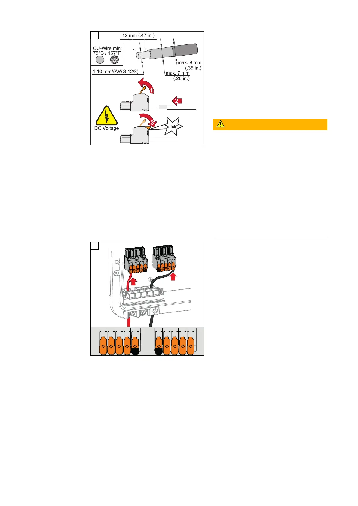
Strip the insulation of the single con-
ductors by 12 mm. Lift to open the ter-
minal's operating lever and insert the
stripped single conductor into the slot
provided, in each case as far as it will
go. Then close the operating lever until
it engages.
WARNING!
Danger due to individual conductors in
the terminal that are loose and/or im-
properly connected.
This can result in serious injury and
damage to property.
▶
Only connect one single conductor
in the slot provided for each ter-
minal.
▶
Check that the single conductor is
held securely in the terminal.
▶
Ensure that all of the single con-
ductor is within the terminal and
that no individual wires are sticking
out of the terminal.
+
PV1
+
PV1
+
PV2
+
PV2
+
BAT
+
PV1
-
PV1
-
PV2
-
PV2
-
BAT
-
-
6
78

 Loading...


