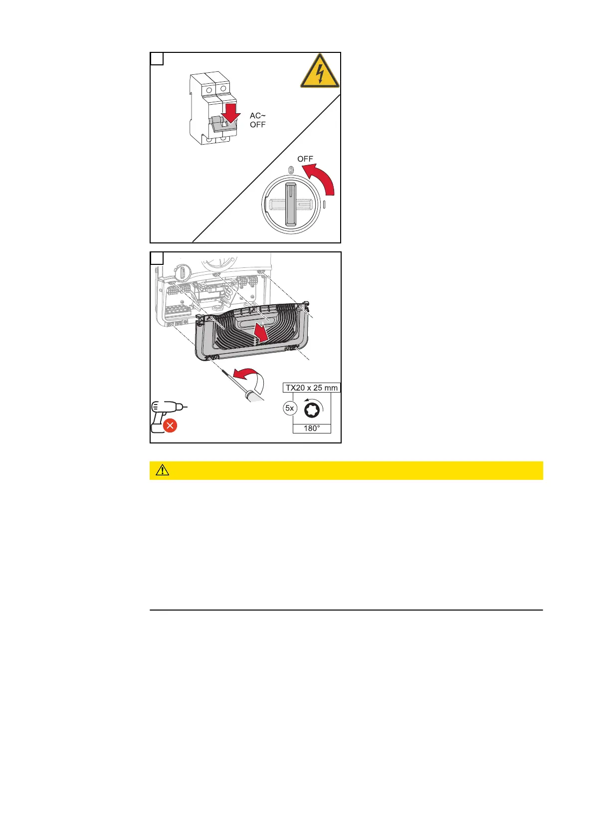
EasyManuals Logo

Fronius Primo GEN24 Series User Manual

Fronius Primo GEN24 Series
232 pages
To Next Page IconTo Next Page
To Previous Page IconTo Previous Page
Page #86 background imageLoading...
Page #86 background image
1
Switch off the automatic circuit break-
er and DC disconnector. Turn the DC
disconnector to the "Off" switch posi-
tion.
2
Loosen the 5 screws of the connection
area cover by rotating them 180° to
the left using a screwdriver (TX20).
Remove the connection area cover
from the device.
CAUTION!
Danger from faulty or incorrect holes.
This may lead to injuries to the eyes and hands as a result of flying debris and
sharp edges, as well as damage to the inverter.
When drilling, wear suitable protective goggles.
Only use a step drill when drilling.
Ensure that nothing is damaged inside the device (e.g. connection block).
Adapt the diameter of the hole to match the corresponding connection.
Deburr the holes using a suitable tool.
Remove the drilling residues from the inverter.
86

Table of Contents

Other manuals for Fronius Primo GEN24 Series

Questions and Answers:

Question and Answer IconNeed help?

Do you have a question about the Fronius Primo GEN24 Series and is the answer not in the manual?

Fronius Primo GEN24 Series Specifications

General IconGeneral
TypeHybrid Inverter
THD< 3 %
Number of MPP trackers2
Max. efficiency98.1 %
Protection classIP66
DC isolationYes
AC Output Power3.0 kW to 10.0 kW
Max. apparent AC power3.0 kVA to 10.0 kVA
Max. output current (at grid voltage)13.0 A to 43.5 A
AC nominal voltage230 V
Number of DC connections2
Operating Temperature Range-25°C to +60°C

Related product manuals