70
Left display Right display
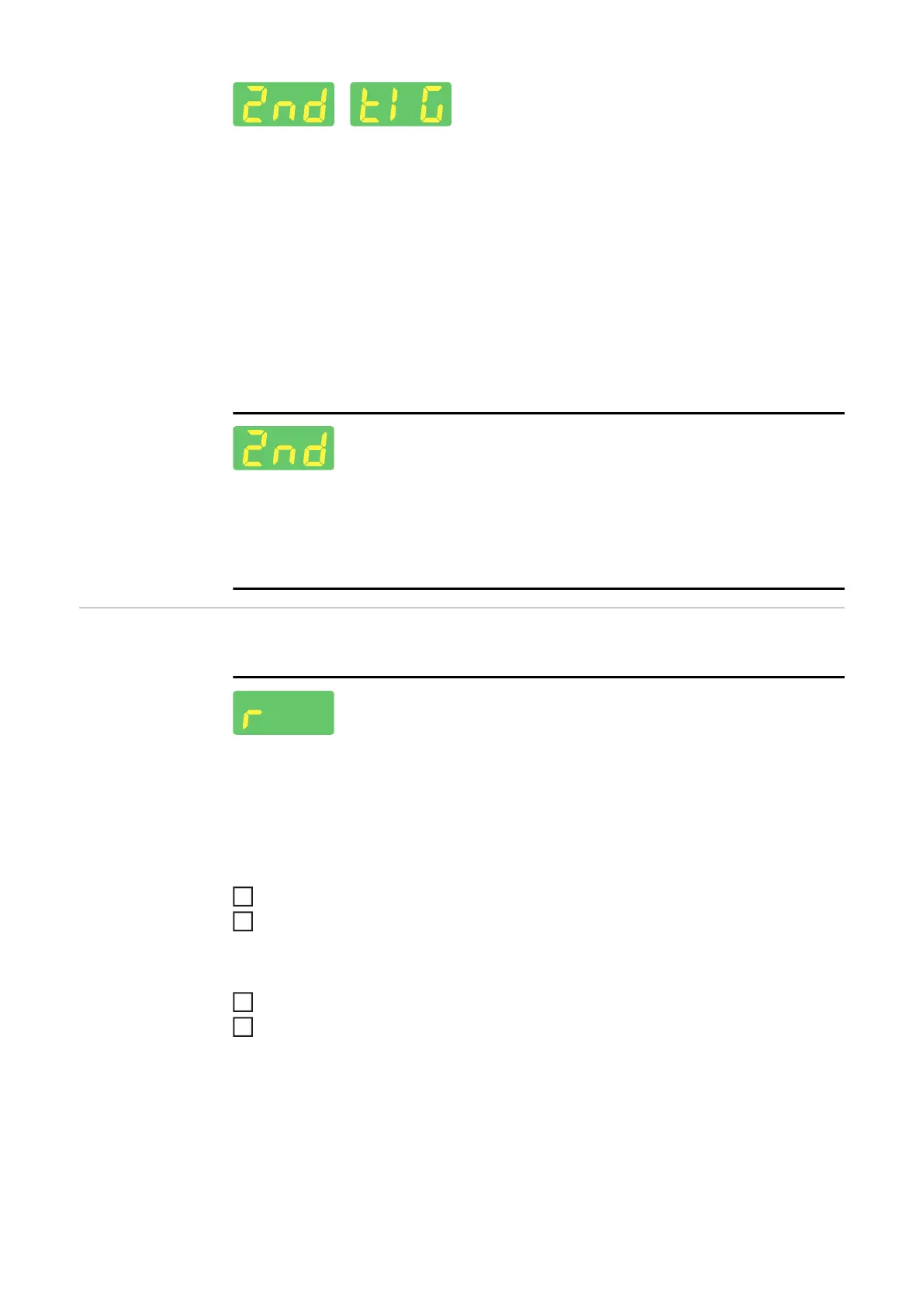
TIG - 2nd level Setup menu
For setting the following parameters:
- r (welding circuit resistance)
- Slope Time 1 (only in 4-step mode)
- Slope Time 2 (only in 4-step mode)
- Trigger
- HF ignition
- Pulse TAC display
- Ignition time out
- Arc break monitoring
- TIG Comfort Stop - Comfort Stop sensitivity
- Break voltage
- Main current changeover
2nd level Setup menu
For viewing "system active time", "system on time", "fuse", and "software version" param-
eters
For setting the "time shut down" parameter
Parameters in the
TIG - 2nd level
Setup menu
The following parameters are available through the second level of the TIG Setup menu:
Welding circuit resistance
For displaying the total resistance of the torch hosepack, welding torch, workpiece, and
grounding cable
IMPORTANT! The ground earth connection and contact of the tungsten electrode must be
made on a cleaned workpiece surface.
Establish a ground earth connection
Select "r" and press the selection dial
The last measured value is displayed on the right display.
Place the tungsten electrode flush against the workpiece surface
Press the torch trigger or gas-test button
The value for "r" is determined, the right display shows "run".
The current value for "r" is then displayed in MOhm on the right display.
If an error occurs while determining the welding circuit resistance, "r" is displayed on the
left display and "Err" is displayed on the right display.
Pressing the torch trigger or the gas-test button restarts the determination of the welding
circuit resistance.
2
3