ASSEMBLY
51
B
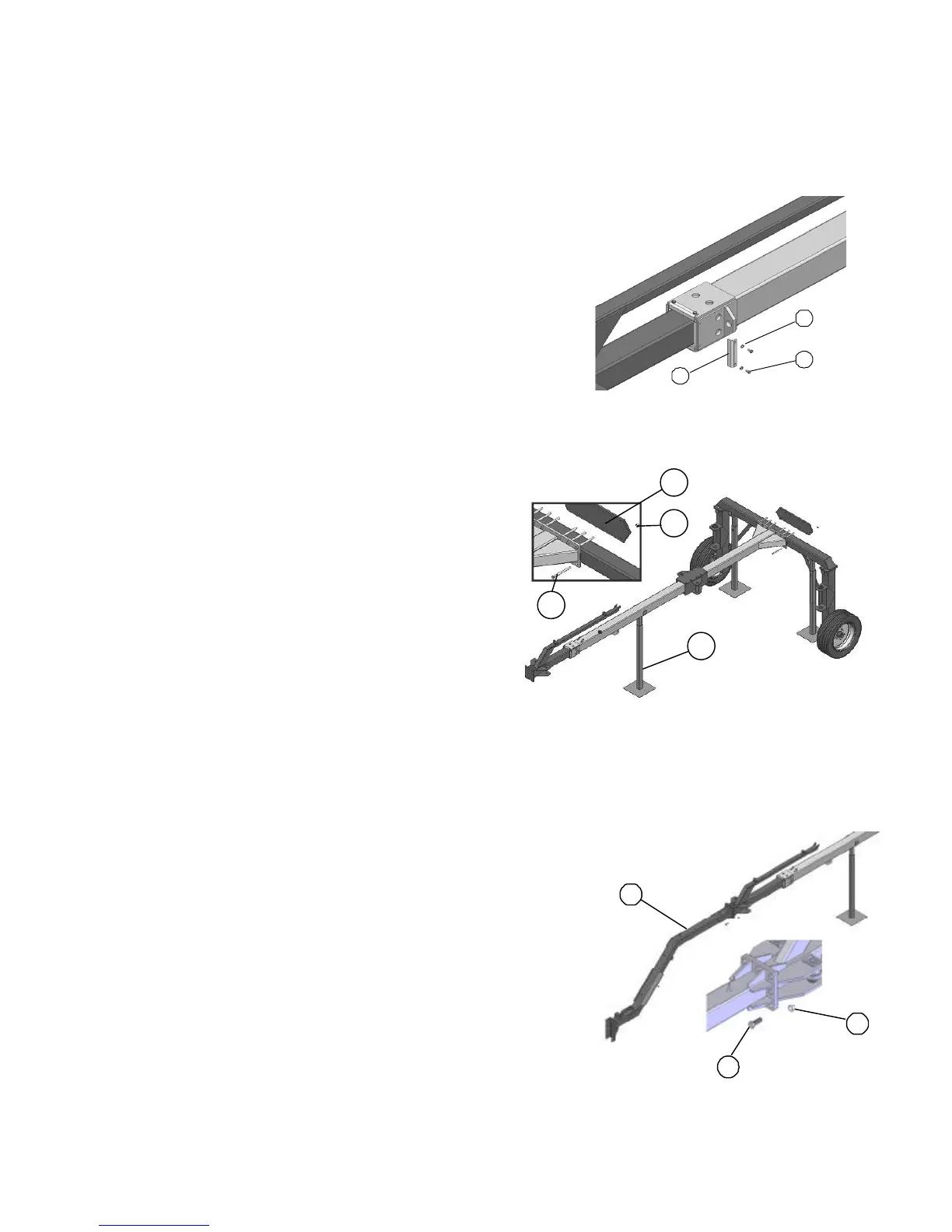
4. Secure the pads with the steel angles (A),
6.4x12.5x1.6 washers (B) and M6x12 cap screw
(C).
A— Steel angels
B— Washers
C— Screws M6x12
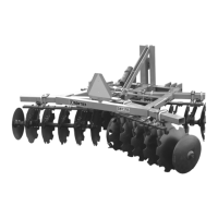
5. Lift the assembled drawbar and connect it to the
rear frames. Support the drawbar with the support
stand (A) positioned as shown in the drawing.
Attach the drawbar with the plate (B), M14x160
cap screw (C), and M14 lock nuts (D).
A— Support stands
B— Plate
C— Screws M14x160
D— Lock nuts M14
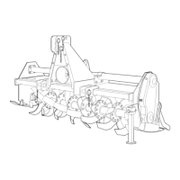
6. Fasten the drawbar (A) with the M14x40 cap
screws (B) and M14 lock nuts (C).
A— Drawbar
B— Screws M14x40
C— Lock nuts M14
D
C
A
B