ASSEMBLY
55
B
B
C
B
C
C D
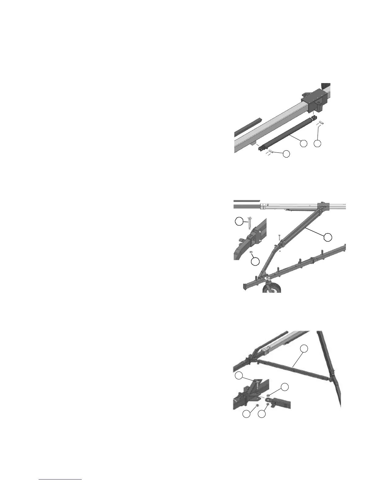
2. Fasten the hydraulic cylinder (A) with cylinder pins
(B) and 5mmx40mm (20inx1.5in) split pins (C).
A— Hydraulic cylinder
B— Pivots
C— Split pins 5x40
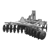
3. Connect the assembled pantograph arms (A) with
M24x174 pivots (B) and M24 locknuts (C).
A— Pantograph arms
B— Pivots M24 174 mm
C— Lock nuts M24
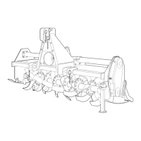
4. Connect the opening arm (A) with a M24x95 pivot
(B) and M24 lock nut assembling as per drawing
the 29X42X15 spacers (C).
A— Arm
B— Pivot M24 95mm
C— Spacers
D— Locknut M24