10-6
17. 10.5.2 Submarine
1. Disconnect electrical power to the fryer.
2. Drain the cooking oil from the frypot.
3. Remove drain system elbow.
4. Remove screw holding contactor box in place. Fig: 10-8
5. Lift contactor box at rear and push backward slightly to
disengage tabs which secure the rear of the box.
6. Lift front of contactor box and pull it forward to create
working room at the rear of the box to remove element
connectors.
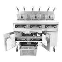
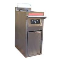
7. Unplug two lower plugs. Fig: 10-17
8. Remove temperature probe per Section 10.4, Steps 1-5, and step 8.
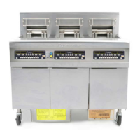
9. Remove mounting hardware on heating elements and lift from unit. Fig: 10-16
10. Remove the heating element wires from the connector. Press down on either side of the connector
while pulling up on the top portion. The connector will open from the top, releasing the wires. Pull
all wires from the connector, noting wire locations in the connector for re-assembly.
11. Install the temperature probe and probe-securing components onto the replacement element.
12. Install the replacement element in the frypot and secure with mounting screws removed in Step 9.
13. Route the element leads (terminals) to the rear of the frypot.
14. When replacing the left element (as viewed from the front of the fryer) insert pin terminals into the
correct holes in the 6-pin connector. When all pins are fully inserted, close the connector by
sliding the halves together until the tabs snap back into place.
15. When replacing the right element (as viewed from the front of
the fryer), use the 9-pin connector. Follow the steps outlined
in Step 11.
16. Insert the connector(s) into the receptacle(s) in the rear of the
contactor box. Be sure the latches lock the connectors in
place.
17. Install the temperature probe wires into the corresponding pin
locations.
18. Feed wires down back of fryer and plug into receptacles on
rear of contactor box.
19. Restore contactor box to its original position, replace element
cap and replace drain elbow.
20. Fill with oil and return fryer to operation.
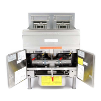
Fig: 10-16
Mounting hardware on fixed-element sub fryer.
Right element
connector
connector
connector
Fig: 10-17