10-7
10.6 Replace High-Limit Thermostat
1. Drain frypot.
2. Remove drain elbow from drain assembly.
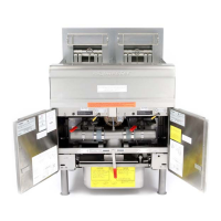
3. Remove screw securing contactor box in place. Lift the contactor box
and push back slightly to release tabs holding the box in the rear of
the cabinet. Lift and pull the box forward to allow access to the plugs
at rear of unit. Fig: 10-8
4. Unplug 15-pin plug from front of contactor box (sub fryer only).
5. Unplug the three plugs on the rear of the contactor box.
6. Remove the element cap.
7. Remove two screws securing controller bezel to fryer’s
frame and pull controller forward to access lower screws.
8. Remove lower bezel screws.
9. Remove controller.
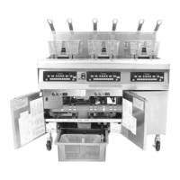
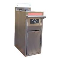
10. Remove screw at front of fryer that holds frypot in place.
Fig: 10-19.
11. Lift frypot from cabinet.
12. Disconnect the wiring harness containing the high-limit
wires.
13. Use a pin pusher (Frymaster Part Number 806-4855) to remove the two high-limit wires from wire
harness connector C6. For split pot fryers, remove only the wires for the high-limit to be replaced.
Mark each wire for re-assembly. Fig: 10-11
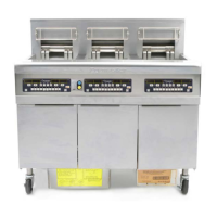
14. Use a 7/8” wrench to remove the high-limit thermostat from the frypot.
15. Apply LocTite PST 567 sealant (enclosed with replacement high -limit) to the threads of the new
high-limit thermostat.
16. Screw the new high-limit into the frypot and tighten securely. DO NOT OVERTIGHTEN!
17. Rest frypot on cabinet sideways, allowing wires to hang near the back of unit.
18. Insert the replacement high-limit wires into the holes in the connector, making certain to insert the
pins into the same two holes from which the old high -limit wires were removed.
19. Position frypot in cabinet
20. Reconnect element wire harnesses to contactor box.
21. Restore contactor box to original location.
22. Replace drain elbow.
23. Replace controller and plug into 15-pin socket on front of contactor box.
24. Install the rear flue covers.
25. Return to service
Fig: 10-19
The removal of one screw behind
the controller allows the frypot to be
Hi-limit probe