LOV
™
Generation II Technical Reference
47
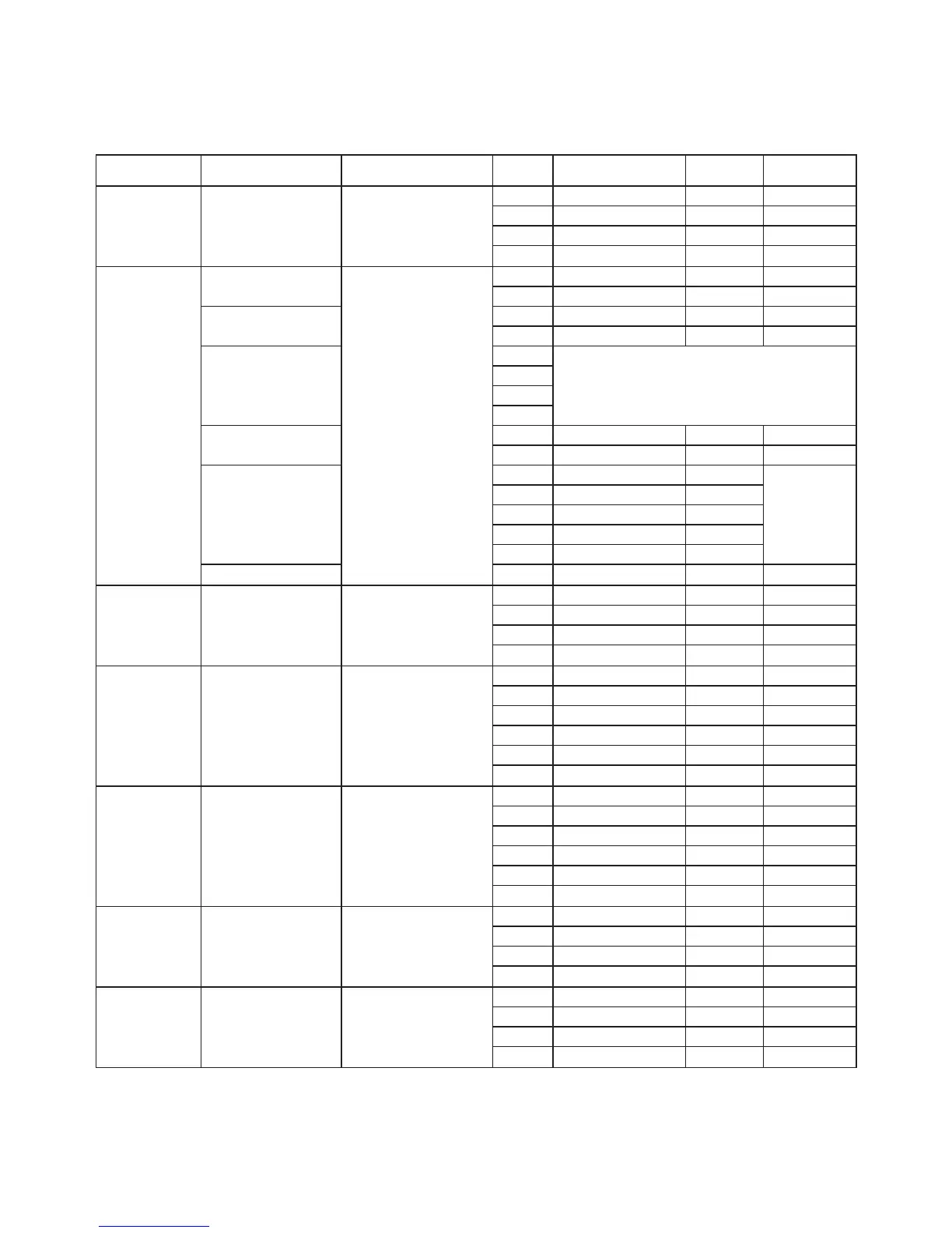
Connector From/To Harness PN Pin # Function Voltage
Wire
Color
J1 FV Return N/A
1 Ret + (Open) 24VDC Black
2 Ret – (Closed) 24VDC Red
3 Ret Position Purple
4 Ground White
J2
FV AIF RTD
1 Ground White
2 FV - Temp Red
DV AIF RTD
3 Ground White
4 DV - Temp Red
5
6
7
8
Oil Level Sensor
(Gas)
9 DV – OLS (Gas) Black
10 FV – OLS (Gas) Red
Locator Pin
11 Locator Vat #5
Black
12 Locator Vat #4
13 Locator Vat #3
14 Locator Vat #2
15 Locator Vat #1
Locator 16 Locator Signal Black
J3 DV Return N/A
1 Ret + (Open) 24VDC Black
2 Ret – (Closed) 24VDC Red
3 Ret Position Purple
4 Ground White
J4
MIB J2 or
AIF J5
8074547
AIF Board
Communication and
Power
1 Ground Black
2 CAN Lo Red
3 CAN Hi White
4 5VDC+ 5VDC Black
5 24VDC 24VDC Red
6 Ground White
J5
AIF J4 or
ATO J10
8074547
AIF Board
Communication and
Power
1 Ground Black
2 CAN Lo Red
3 CAN Hi White
4 5VDC+ 5VDC Black
5 24VDC 24VDC Red
6 Ground White
J6 FV Drain N/A
1 Drain + (Open) 24VDC Black
2 Drain – (Closed) 24VDC Red
3 Drain Position Purple
4 Ground White
J7 DV Drain N/A
1 Drain + (Open) 24VDC Black
2 Drain – (Closed) 24VDC Red
3 Drain Position Purple
4 Ground White
AIF (Auto Intermittent Filtration) Actuator Board Pin Positions