2-10
e DC reactor terminals, P1 and P (+)
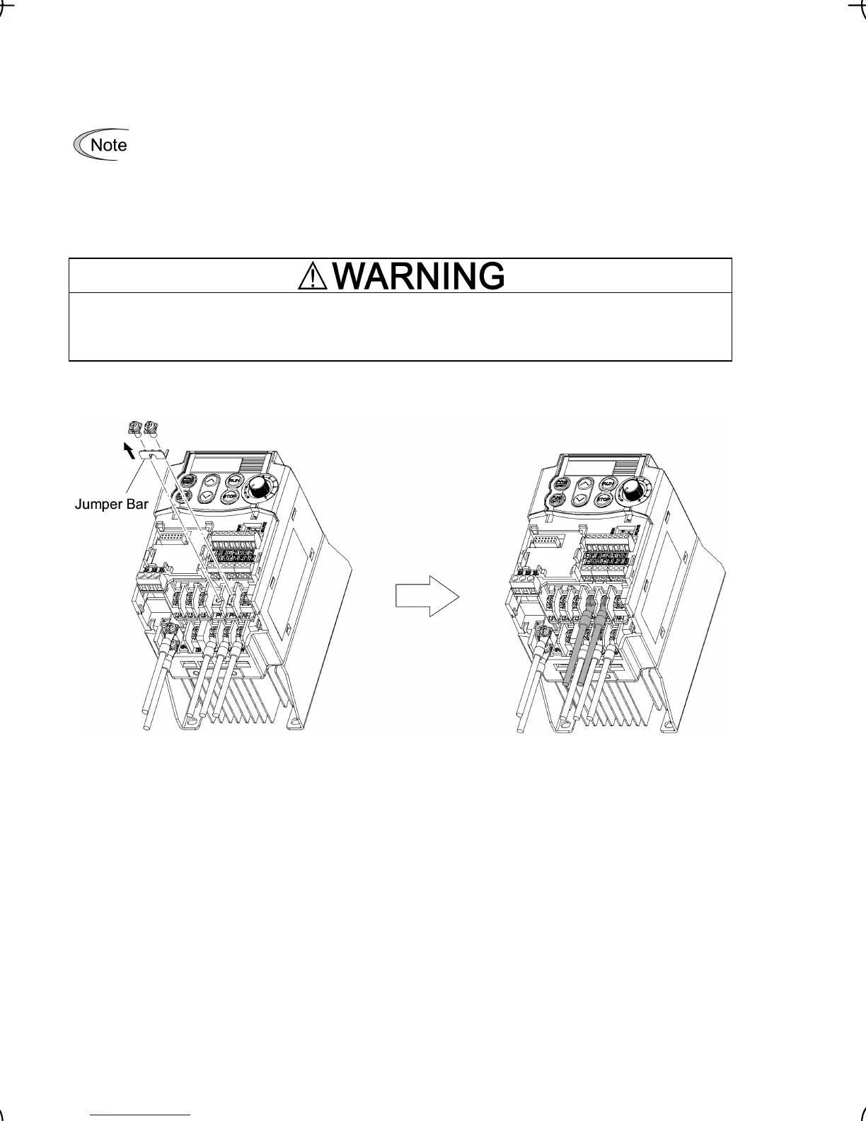
1) Remove the jumper bar from terminals P1 and P(+).
2) Connect a DC reactor (option) to terminals P1 and P(+).
• The wiring length should be 10 m or below.
• If both a DC reactor and a braking resistor are to be connected to the inverter, secure
both wires of the DC reactor and braking resistor together to terminal P(+). (Refer to
item
f on the next page.)
• Do not remove the jumper bar if a DC reactor is not going to be used.
When wiring the inverter to the power supply of 500 kVA or more (50 kVA or more for the sin-
gle-phase 100 V class series of inverters), be sure to connect an optional DC reactor (DCR).
Otherwise, fire could occur.
Figure 2.6 DC Reactor Connection

 Loading...


