02-01
2-1 ERROR DISPLAY
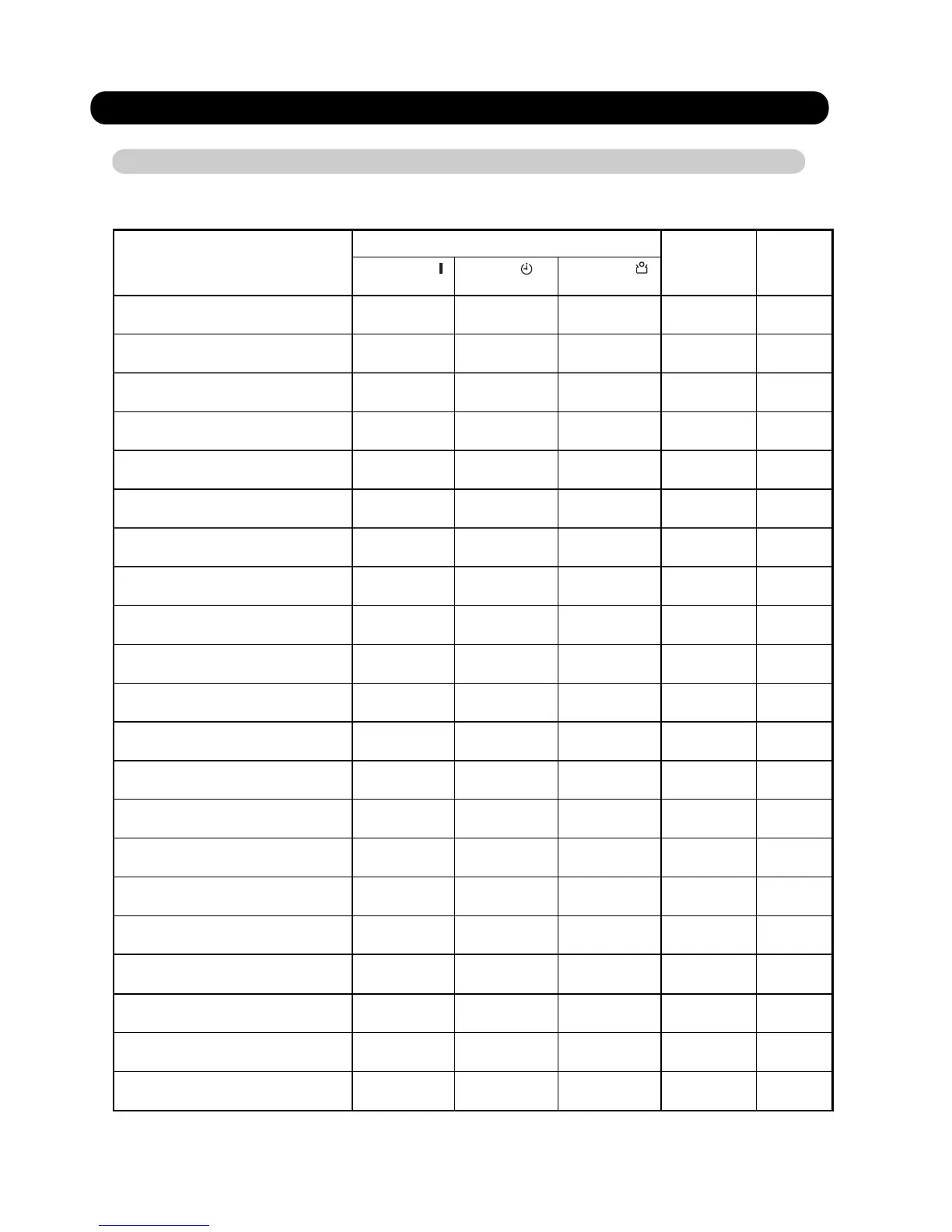
2-1-1 INDOOR UNIT AND WIRED REMOTE CONTROLLER DISPLAY
Please refer the flashing pattern as follows.
The OPERATION, TIMER and ECONOMY lamps operate as follows according to the error contents.
Manual auto switch error
Room temp. sensor error
Indoor unit PCB model
information error
Wired remote controller
communication error
Error Contents
Continuous
Continuous
4 times
Continuous
2 times
3 times
3 times
5 times
Continuous2 times1 times
Continuous1 times1 times
Trouble
shooting
(Green)
(Orange)
(Green)
1 times
Serial communication error
3 times2 times
Combination error
Indoor unit fan motor error
Indoor unit Heat Ex. Middle temp.
sensor error
Continuous
4 times 2 times
Continuous
Continuous
1 times5 times
Outdoor unit main PCB model
information error
2 times6 times
3 times6 times
Continuous
Continuous
4 times
7 times
6 times
1 times
Continuous
7 times 3 times
Continuous
7 times 4 times
Continuous
PFC circuit error
Inverter error
Discharge temp. sensor error
Outdoor unit Heat Ex. liquid
temp. sensor error
Outdoor temp. sensor error
1
2
3
4
5
6
7
8
9
10
11
12
13
14
15
16
17
18
19
20
21
Continuous
8 times 4 times
Current sensor error
Continuous
Continuous
Continuous
5 times
9 times
9 times
7 times
Compressor rotor position
detection error
Outdoor unit fan motor error
Continuous
4 times9 times
Continuous
Continuous
9 times 9 times
4-way valve error
1 times10 times
Discharge temp. error
Trip detection
Continuous
5 times6 times
Trip terminal L error
Indoor Unit Display
Wired Remote
Controller
Display
11
12
23
32
35
41
42
51
62
63
64
65
71
73
74
84
94
95
97
99
A1
[ ]
[ ]
[ ]
OPERATION TIMER
ECONOMY
2. TROUBLESHOOTING
 Loading...