En-7
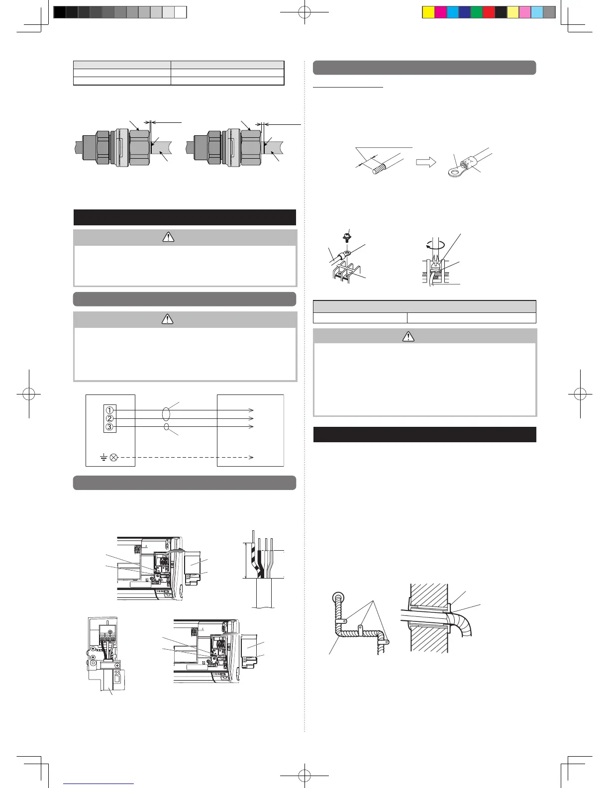
7.3. How to connect wiring to the terminals
Caution when wiring cable
To strip off the insulation of a lead wire, always use a special tool such as a wire strip-
per. If there is no special tool, carefully strip off the insulation by using a knife or other
utensil.
(1) Usecrimp-type ringterminalswithinsulatingsleeves asshown intheguretocon-
nect to the terminal block.
(2) Securelyclampthecrimp-typeterminalstothewiresbyusinganappropriatetoolso
that the wires do not come loose.
Strip:10mm
Crimp-type
terminal
Sleeve
(3) Connectspeciedwiressecurely,andfastenthemsothatthereisnostressapplied
on the terminals.
(4) Useascrewdriverwithanappropriatebitsizetotightentheterminalscrews.Usingof
screwdriver with inappropriate bit size will damage the screw heads, and the screws
will not be tightened properly.
(5) Donotovertightentheterminalscrews.Otherwise,thescrewsmaybreak.
Screw with special washer
Wire
Crimp-type terminal
Terminal blocks
Wire
Screw with special washer
Crimp-type
terminal
(6) Seethetablefortheterminalscrewtighteningtorques.
Tighteningtorque[N·m(kgf·cm)]
M4 screw 1.2to1.8(12to18)
CAUTION
• Match the terminal block numbers and connection cable colors with those of the
outdoorunit.Incorrectwiringmaycauseare.
•Connecttheconnectioncablesrmlytotheterminalblock.Imperfectinstallationmay
causeare.
•Whenxingtheconnectioncablewiththecableclamp,alwaysfastenthecableatthe
plastic jacket portion, but not at the insulator portion. If the insulator is chafed, electric
leakage may occur.
•Alwaysconnecttheearth(ground)wire.Improperearthing(grounding) work can
cause electric shocks.
•Donotusetheearth(ground)screwfortheindoorunittotheoutdoorunitunlessitis
specied.
8. FINISHING
(1) Insulatebetweenpipes.
• Insulatesuctionanddischargepipesseparately.
• Forrear,right,andbottompiping,overlaptheconnectionpipeheatinsulationand
indoor unit pipe heat insulation and bind them with vinyl tape so that there is no gap.
• Forleftandleftrearpiping,butttheconnectionpipeheatinsulationandindoorunit
pipe heat insulation together and bind them with and vinyl tape so that there is no gap.
• Forleftandleftrearpiping,wraptheareawhichaccommodatestherearpiping
housing section with cloth tape.
• Forleftandleftrearpiping,bindtheconnectioncabletothetopofthepipewith
vinyl tape.
• Forleftandleftrearpiping,bundlethepipinganddrainhosetogetherbywrapping
themwithclothtapeovertherangewithinwhichtheytintotherearpiping
housing section.
(2) Temporarilyfastentheconnectioncablealongtheconnectionpipewithvinyltape.
(Wraptoabout1/3thewidthofthetapefromthebottomofthepipesothatwater
doesnotenter.)
(3) Fastentheconnectionpipetotheoutsidewallwithasaddle,etc.
(4) Fillthegapbetweentheoutsidewallpipeholeandthepipewithsealersothatrain
water and wind cannot blow in.
(5) Fastenthedrainhosetotheoutsidewall,etc.
*Fieldsupplied
Pipe
Saddle*
Outsidewallcap*
Sealerputty*
(Outdoors)
Wall
Tighteningnut[mm(in.)] Tighteningtorque[N·m]
6.35(1/4)dia. 16 to 18
12.70(1/2)dia. 49 to 61
Step.6 Confirm that the marking on the connection pipe is within 1mm from the
tightening nut.
GOOD PROHIBITED
If the insert margin marking is more than 1mm away from the tightening nut, remove the
arelessjointnutassy,replacewithanewarelessjointnutassy,andstartworkfrom6.9.1.
PleaserefertotheServiceInstructiontoremovethearelessjointnutassy.
7. ELECTRICAL WIRING
CAUTION
Becarefulnottogenerateasparkasfollowsforusingaammablerefrigerant.
Donotremovethefusewhilethepowerison.•
Donotdisconnectthewiringwhilethepowerison.•
Itisrecommendedtopositiontheoutletconnectioninahighposition.Placethe•
cords so that they do not get tangled.
7.1.
Wiring system diagram
WARNING
• Before connecting the wires, make sure the power supply is OFF.
•Everywiremustbeconnectedrmly.
•Nowireshouldbeallowedtotouchrefrigeranttubing,thecompressor,oranymov-
ing part.
•Loosewiringmaycausetheterminaltooverheatorresultinunitmalfunction.Are
hazardmayalsoexist.Therefore,besureallwiringistightlyconnected.
• Connect wires to the matching numbers of terminals.
Earth(Ground)line
OUTDOORUNIT
Pleaseconnecttothe
speciedterminal.
INDOORUNIT
TERMINAL
Powerline
Control line
7.2.
Indoor unit wiring
1.Removethewirecover.(Remove1screw.)
2. Remove the cable clamp.
3.Bendtheendoftheconnectioncableasshowninthegure.
4. Connect the end of the connection cable fully inserting into the terminal block.
5.Fastentheconnectioncablewithacableclamp.
Wirecover
Wirecover
Screw
Screw
Screw
Screw
Insert the wire cover tab into the square hole
of the indoor unit and fasten with a screw.
Connection cable
60 mm
40 mm
Cable clamp
Cable clamp
 Loading...