En-9
11. REMOTE CONTROLLER INSTALLATION
Check that the indoor unit correctly receives the signal from the remote controller, then
install the remote controller holder.
CAUTION
Donotinstalltheremotecontrollerholderinthefollowingconditions:
•Anyplacesexposedindirectsunlight
•Positionsaffectedbytheheatfromastoveorheater
11.1. Remote controller holder installation
•
Installtheremotecontrolleramaximumdistanceof7mfromtheremotecontrolsignal
receiver.Afterinstallingtheremotecontroller,checkthatitoperatescorrectly.
•
I
nstall the remote controller holder to a wall, pillar, etc. with the tapping screw.
Remote controller
holder xing
Remote controller
mounting
Remote controller
holder
Tapping
screw
(small)
(1)Set
Remote
controller
(2)Down
12. OPTIONAL KIT INSTALLATION
This air conditioner can be connected with the following optional kits.
• Wiredremotecontroller
• Simpleremotecontroller
• Externalconnectkit
BEFORE INSTALLING THE WIRED REMOTE CONTROLLER
• Whenyouusewiredremotecontroller,somefunctionsmaynotbeused.
CAUTION
•Beforeinstallation,makesurethatallpowersupplieshasbeendisconnected.
•Donottouchthealuminumnsofheatexchangerbuilt-intheindoororoutdoorunitto
avoid personal injury when you install or maintain the unit.
•Intheinstallationorremoval,besurenottohaveanywiresgettingcaughtbyparts
orgettinganextremetension.Excessivepressureortensiontothewiremaycause
malfunction of the air conditioner.
•Avoidanyplacesexposedindirectsunlight.
•Chooseapositionthatwillnotbeaffectedbytheheatfromastoveorheater.
•Beforesettinguptheoptionalkit,conrmwhethertheair-conditionerreceivesthe
signal from the remote controller.
•Donotconnectthewiredremotecontrollertotheterminalforpowersupply.
•Whenconnectingthewiredremotecontrollerwiththeindoorunit,usetheconnecting
cable that is supplied with wired remote controller or simple remote controller.
•Recommendedcablelengthofwiredremotecontrolleris10m.Whenyouextendthe
cable, insulate the connecting part of the cable.
Donotconnectpowersupplywiththeterminal.
INDOORUNIT
PCB
TERMINAL
13.
INSTALLATION WORK
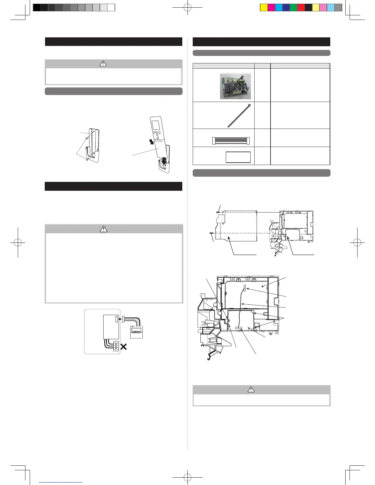
13.1. Accessories (Communication kit)
Thefollowinginstallationaccessoriesaresupplied.Usethemasrequired.
Name and Shape
Q’ty
Description
Relay control board
1
For connecting the
wired remote control
unitandexternal
connect wire.
Cable tie
1
Forxingthewires
fromcontrolbox.
Relay wire
1
For connecting the
relay control board and
control unit board.
Wiringlabel
1
For displaying the additional
wiring diagram.
13.2. Installation work
13.2.1. Removing intake grille and front panel
(See “9.
FRONTPANELREMOVALANDINSTALLATION”
and“9.1.Frontpanelremoval”)
13.2.2. Removing control cover
Screw 2
Control cover Controlbox
Screw 1
Remove the screw 1 and 2, then remove the control cover.
13.2.3. Installing relay control board and relay wire terminal
Control unit board
Connector(CN2)
Relay wire
Notice*2.
Clasps
Connector(CND01)
Relay control board
Clasp
*2.Notice the installingdirection
of the relay control board. (The
elevation of thecontrolbox is
fit for the recess of the relay
controlboard.)
(1)Inserttherelaycontrolboardtoward2clasps.
(2)Thensettheboardwiththeclasp.
(3)Connecttherelaywireterminaltotheconnector(CND01)ontherelaycontrolboard.
(4)Connecttherelaywireterminaltotheconnector(CN2)onthecontrolunitboard.
CAUTION
Be careful not to damage the parts on the board.
Otherwise, it will cause malfunction.
 Loading...