En-4
2.2. Accessories
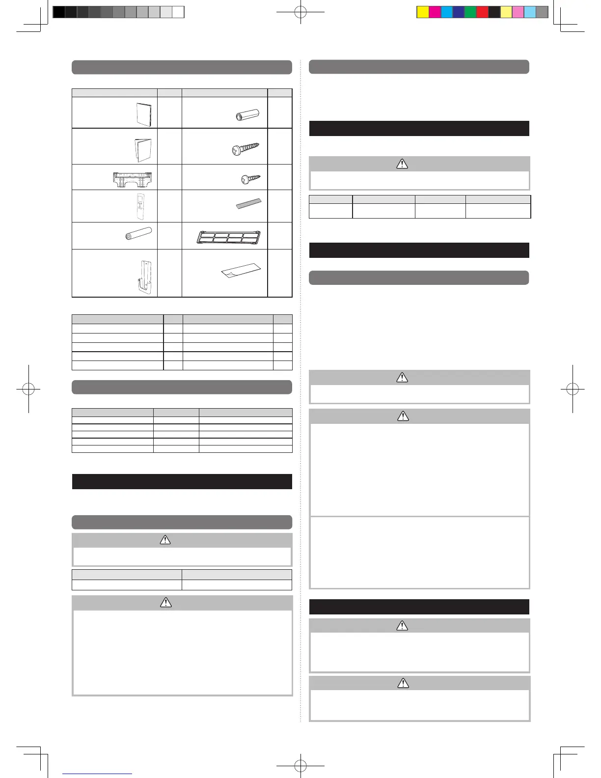
Thefollowinginstallationaccessoriesaresupplied.Usethemasrequired.
Name and Shape
Q’ty
Name and Shape
Q’ty
Operating Manual
1
Cloth tape
1
Installation Manual
(Thismanual)
1
Tapping screw
(M4×25mm)
5
Wallhookbracket
1
Tapping screw
(M3×12mm)
2
Remote controller
1
Aircleaningfilter
2
Battery
2
Filter holders
2
Remote controller holder
1
SealA
1
The following items are necessary to install this air conditioner. (The items are not includ-
edwiththeairconditionerandmustbepurchasedseparately.)
Name Q’ty Name Q’ty
Connection pipe assembly 1 Wallcap 1
Connectioncable(4-conductor)
1 Saddle 1 set
Wallpipe 1 Drainhose 1
Decorativetape 1 Tapping screws 1 set
Vinyltape 1 Sealant 1
2.3. Optional parts
Refer to each installation manual for the method of installing optional parts.
Parts name Model name Application
WiredRemoteController* UTY-RVNYN For air conditioner operation
WiredRemoteController* UTY-RNNYN For air conditioner operation
SimpleRemoteController* UTY-RSNYN For air conditioner operation
Externalconnectkit* UTY-XWZXZ5 Forcontrolinput/outputport
Communication kit UTY-TWBXF1 For the installation of optional parts
*Optionalcommunicationkitisnecessaryfortheinstallation.
3. GENERAL SPECIFICATION
ThisINSTALLATIONMANUALbrieyoutlineswhereandhowtoinstalltheairconditioningsystem.
Pleasereadover the entiresetof instructions fortheindoor and outdoorunitsand make sureall
accessory parts listed are with the system before beginning.
3.1. Type of copper pipe and insulation material
CAUTION
For appropriate pipe length and height difference, refer to the installation manual for the
outdoor unit.
Gas pipe size (thickness) [mm] Liquid pipe size (thickness) [mm]
Ø
12.70(0.8)
Ø
6.35(0.8)
CAUTION
•Wrapheatinsulationaroundbothofthegaspipeandtheliquidpipe.
Noheat-insulationworkorincorrectheat-insulationworkmaycausewaterleaks.
•Inareversecyclemodel,useheatinsulationwithheatresistanceabove120
°C
.
•Ifexpectedhumidityoftheinstallationlocationofrefrigerantpipesishigherthan70%,
wrap the heat insulation around the refrigerant pipes.
Iftheexpectedhumidityisbetween70%and80%,useheatinsulationthathas
thicknessof15mmormore.
Iftheexpectedhumidityishigherthan80%,useheatinsulationthathasthickness
of 20 mm or more.
•Usingofthinnerheatinsulationthanspeciedabovemaycauseacondensationon
the surface of the insulation.
•Useheatinsulationwiththermalconductivityof0.045W/(
m•K
)orless,at20
°C
.
3.2. Additional materials required for installation
A.Refrigeration(armored)tape
B.Insulatedstaplesorclampsforconnectingwire(Seeyourlocalelectricalcodes.)
C.Putty
D.Refrigerationlubricant
E. Clamps or saddles to secure refrigerant piping
4. ELECTRICAL REQUIREMENT
Theindoorunitispoweredfromtheoutdoorunit.Donotpowerindoorunitfromseparate
power source.
WARNING
Standard for electrical wiring and equipment differs in each country or region. Before you
startelectricalworking,conrmrelatedregulations,codes,orstandards.
Cable
Conductor size [
mm
2
] Type
Remarks
Connection cable
1.5-2.5 Type60245IEC57
3 cable +
Earth(Ground)
,
1Ø240V
Max.CableLength: Limit voltagedrop to lessthan2%. Increasecablegauge if voltage
dropis2%ormore.
5. SELECTING THE MOUNTING POSITION
Decidethemountingpositionwiththecustomerasfollows:
5.1. Indoor unit
(1) Installtheindoorunitlevelonastrongwallwhichisnotsubjecttovibration.
(2) Theinletandoutletportsshouldnotbeobstructed:theairshouldbeabletoblowall
over the room.
(3)
Install the unit a dedicated electrical branch circuit.
(4)
Donotinstalltheunitwhereitwillbeexposedtodirectsunlight.
(5)
Install the unit where connection to the outdoor unit is easy.
(6) Installtheunitwherethedrainpipecanbeeasilyinstalled.
(7) Takeservicing,etc.intoconsiderationandleavethespacesshownin“6.1.Installation
dimensions”.Alsoinstalltheunitwheretheltercanberemoved.
Correctinitialinstallationlocationisimportantbecauseitisdifculttomovetheunitafterit
is installed.
WARNING
Installtheunitwhereiscapabletosupporttheweightoftheunit.Securetheunitrmly
so that the unit does not topple or fall.
CAUTION
Donotinstalltheunitinthefollowingareas:
•Areawithhighsaltcontent,suchasattheseaside.Itwilldeterioratemetalparts,caus-
ing the parts to fail or the unit to leak water.
•Arealledwithmineraloilorcontainingalargeamountofsplashedoilorsteam.Itwill
deteriorate plastic parts, causing the parts to fail or the unit to leak water.
•Areawhereisclosetoheatsources.
•Areathatgeneratessubstancesthatadverselyaffecttheequipment,suchassulfuric
gas, chlorine gas, acid, or alkali. It will cause the copper pipes and brazed joints to cor-
rode, which can cause refrigerant leakage.
•Areathatcancausecombustiblegastoleak,containssuspendedcarbonbersor
ammabledust,orvolatileinammablessuchaspaintthinnerorgasoline.
•Ifgasleaksandsettlesaroundtheunit,itcancauseare.
•Areawhereanimalsmayurinateontheunitorammoniamaybegenerated.
•Donotuseforpreservationoffood,plants,animals,precisionequipment,artwork,or
other objects. This may cause quality deterioration of those items.
•Installtheunitwheredrainagedoesnotcauseanytrouble.
•Installtheindoorunit,outdoorunit,powersupplycable,transmissioncable,andre-
mote control cable at least 1 m away from a television or radio receivers. The purpose
ofthisistopreventTVreceptioninterferenceorradionoise.
(Even if they are installed more than 1 m apart, you could still receive noise under
somesignalconditions.)
•Ifchildrenmayapproachtheunit,takepreventivemeasuressothattheycannotreach
the unit.
•Installtheindoorunitonthewallwheretheheightfromtheoorismorethan1.8m.
6. INSTALLATION WORK
WARNING
Duringtransportationorrelocationoftheindoorunit,pipesshallbecoveredwiththe
wallhookbracketforprotection.Donotmovetheappliancebyholdingtheindoorunit
pipes.
(Thestressappliedtothepipejointsmaycausetheammablegastoleakduring
operation.)
CAUTION
•Donothitorpushthehumansensor.Thismayleadtodamageormalfunction.
•Donottouchthehumansensor.Anyscratchesordirtmayleadtoincorrectdetection.
•Donotplacelargeobjectsnearthe
human
sensor.Alsokeepheatingunitsoutsidethe
sensor’s detection area.