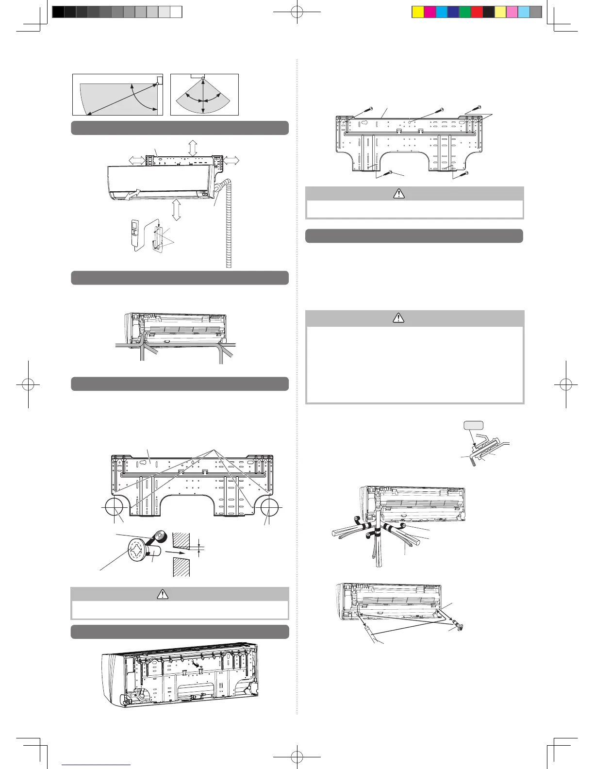
Detectionrangeofthe
human
sensor is as follows.
Verticalangle90°(Sideview) Horizontalangle100°(Topview)
6.1. Installation dimensions
127 mm or over
1.5morover
Remote
controller
Remote controller holder
Tappingscrew(small)
1.8 m
or over
(Wallcap)
84 mm
or over
Wallhook
bracket
133 mm or over
6.2. Indoor unit piping direction
The piping can be connected in the
6
directions indicated in the following.
Whenthepipingisconnectedtodirection(2),(3),(4)or(5),
cut along the piping groove
on the side of the front cover with a hacksaw.
(2)
Right
outlet
(5)
Left
outlet
(6)
Left rear
outlet
(3)
Bottom outlet
(1)
Rear outlet
(4)
Left bottom outlet
(Rear)
6.3.
Cutting the hole in the wall for the connecting piping
(1) Cuta65mmdiameterholeinthewallatthepositionshowninthefollowing.
(2) Cuttheholesothattheoutsideendislower(5to10mm)thantheinsideend.
(3) Alwaysalignthecenterofthewallhole.Ifmisaligned,waterleakagewilloccur.
(4)
Cut the wall pipe to match the wall thickness, stick it into the wall cap, fasten the cap with
vinyl tape, and stick the pipe through the hole.
(5) Forleftpipingandrightpiping,cuttheholealittlelowersothatdrainwaterwillow
freely.
Wall
Fasten with
vinyl tape
65mmdia.hole
65mmdia.hole
Wallhookbracket Center mark
Wallcap*
Wallpipe*
(Inside) (Outside)
5to10mmlow
*Fieldsupplied
WARNING
Alwaysusethewallpipe.Ifthewallpipeisnotused,thecablethatisconnectedbetween
the indoor unit and the outdoor unit may touch metal, and cause an electric discharge.
6.4. Installing the wall hook bracket
•Removethewallhookbracketfromtheindoorunit.(Removescrew).
(1)Installthewall hook bracket so that it is correctly positioned horizontally and vertically.
Ifthewallhookbracketistitled,waterwilldriptotheoor.
(2)
Install the wall hook bracket so that it is strong enough to support the weight of the unit.
•
Fastenthewallhookbrackettothewall with5ormorescrewsthroughtheholesnearthe
outer edge of the bracket.
•
Check that there is no rattle at the wall hook bracket.
Wallhookbracket
Tapping screw
CAUTION
Install the wall-hook bracket both horizontally and vertically aligned.
Misaligned installation may cause water leakage.
6.5.
Forming the drain hose and pipe
[Rear piping, Right piping, Bottom piping]
•Install theindoorunit pipingin thedirectionof thewall holeandbindthedrain hose
and pipe together with vinyl tape.
•Installthepipingsothatthedrainhoseisatthebottom.
•Wrapthepipesoftheindoorunitthatarevisiblefromtheoutsidewithdecorativetape.
[For Left rear piping, Left piping]
Interchange the drain cap and the drain hose.
CAUTION
•Insertdrainhoseanddraincapsecurely.Drainshould slope down to avoid water leakage.
•Wheninsertingthedrainhose,noothermaterialthan watershouldbe applied.
Applicationofothermaterialthanwaterwillcausedeteriorationofthehose,andmay
cause water leakage.
•Afteryouremoveadrainhose,besuretoattachthedraincap.
•Whenyousecurethepipinganddrainhosewithtape,arrangethedrainhosesothat
it is at the bottom of the piping.
•Fordrainhosepipinginlowtemperatureenvironment,youneedtoapplyfreeze
protection to prevent a frozen drain hose.
Aftercoolingoperationisperformedinlowtemperatureenvironment,(whenoutdoor
temperatureunder0°C,)waterinthedrainhosecouldbefrozen.Frozendrainwater
willblockthewaterowinthehose,andmaycausewaterleakageattheindoorunit.
Installing the Drain cap
Useahexagonalwrench4mmatoppositesideto
insert the drain cap, till the drain cap contacts the tip
of the drain cock.
Right piping
Bottom piping
Bind with vinyl tape
Refrigerantpipes(top)
Rear piping
Indoorunitdrainhose(bottom)
For left outlet piping,
cut off the piping
outlet cutting groove
with a hacksaw.
Indoor unit
drain hose
Draincap
Remove the drain cap by pull-
ing at the projection at the end
of the cap with pliers, etc.
Nogap
Hexagonal
wrench
Drain
cock
Draincap
 Loading...