Chapter 2 Components
2.1 Controller Enclosure
ETERNUS DX80 S2/DX90 S2 Disk storage system User’s Guide -Installation-
Copyright 2013 FUJITSU LIMITED P3AM-4832-07ENZ0
32
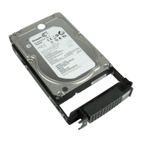
● Part explanation
• LEDs
The states of LEDs are listed below.
Table 2.2 Status and meanings of each LED (drive)
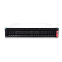
2.1.4 Components (Rear)
This section describes the controllers and the power supply units in the rear of the controller enclosure.
2.1.4.1 Controllers
The controller contains a CPU, cache memory, System Capacitor Unit (SCU), host interfaces, drive interface (DI)
ports, and LAN ports. The controller controls all operations in the ETERNUS DX Disk storage system.
Figure 2.11 Controller
LED name LED status Drive status
DRIVE READY
(green)
The drive is in normal status.
(blinks green)
DRIVE FAULT
(amber)
• The drive is in error status.
• In response to commands from ETERNUS CLI, the location of the
drive is identified.
LAN (MNT) port
ACT LED
LINK LED
DI (OUT) LINKUP LED
READY/FAULT LED
MASTER LEDUNIT ID LED
CA#0 FAULT LED
PWC port
LINK/FAULT LED
DI (OUT) port
LAN (RMT) port
Host interface (CA#0)
Host interface (CA#1)
CA#1 FAULT LED

 Loading...