SYSTEM CONFIGURATION
xiii
TZTBB
Note 1: Do not connect or disconnect the DVI cable between TZTBB and the touch monitor while
TZTBB is powered.
Note 2: When connecting two monitors, resolutions and aspect should match between two mon-
itors. Both screens show same images (compatible with clone mode only).
RADAR SENSOR
DRS2D/DRS4D
OR
RADAR SENSOR
DRS4A/DRS6A/DRS12A/DRS25A
12-24 VDC
CCD Camera
CCD Camera
FI-5002
SC-30
GP-330/WS-200
FI-50, etc.
IF-NMEA2K1/2
12/24 VDC
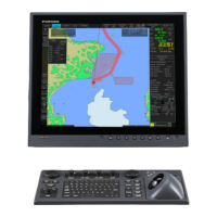
Touch Monitor
Event SW
External Buzzer
Speed Alarm
Power input for CAN bus
HUB -101
FCV-1150, BBDS1, DFF series
FA-30/50
IP Camera
Environmental category
Sensor units: Exposed to the weather
All other units: Protected from the weather
FAX-30
NAVpilot-700
Touch Monitor
Switch Box
PSD-002
Processor Unit
MPU-002
12-24 VDC
POWER SUPPLY UNIT*
PSU-017
POWER SUPPLY UNIT*
PSU-012/PSU-013
*: The power supply unit is required when you connect the radar sensor.
PSU-012: w/DRS2D/4D/4A/6A/12A
PSU-013: w/DRS25A
PSU-017: w/DRS2D/4D
For details of the power supply unit, see the installation manual of the radar sensor (IME-35670).
FUSION-Link equipment
Network equipment
FAR-2xx7 series
MCU-002
 Loading...