25
Output
connector
Channel
Mode A
1
~
8CH
Mode B
1
~
7CH
Mode C
9
~
16CH
Mode D
9
~
15CH
1 1 1 9 9
2 2 2 10 10
3 3 3 11 11
4 4 4 12 12
5 5 5 13 13
6 6 6 14 14
7/B 7 7 15 15
8/SB 8 S.BUS 16 S.BUS
Red LED
blink
1 time 2 times 3 times 4 times
R7108SB CH Mode table
Default
Channel Modes
The R7108SB is capable of changing its channel allocations as
described in the table below. This is especially important when
using the receiver in a dual receiver mode.
1
Turn on the receiver. [Transmitter is always OFF]
2
Press and hold the Link/Mode button for 5 seconds to 10
seconds.
3
When the LED of the receiver changes from blinking red
to blinking red with green, Link/Mode button is released.
4
The LED should now blink red two times in the patterns
described in the chart below.
5
Each press of the Link/Mode button advances the
receiver to the next mode.
6
When you reach the mode that you wish to operate in,
press and hold the Link/Mode button for more than 2
seconds.
When LED blinks in green with red, it is the
completion of a mode change, Link/Mode button is
released.
7
Please cycle the receiver power off and back on again
after changing the Channel mode.
LED Indication
System Status LED
FASSTest
No signal reception Red Solid
Receiving signals Green Solid
Waiting for link
Start → 2second
later → Red
Blink(1second)
FASST
No signal reception Red Solid
Receiving signals Green Solid
Receiving signals
but ID is unmatched
Green Blink
Waiting for link Red Blink
FASSTest
FASST
Unrecoverable error
(EEPROM, etc.)
Alternate blink
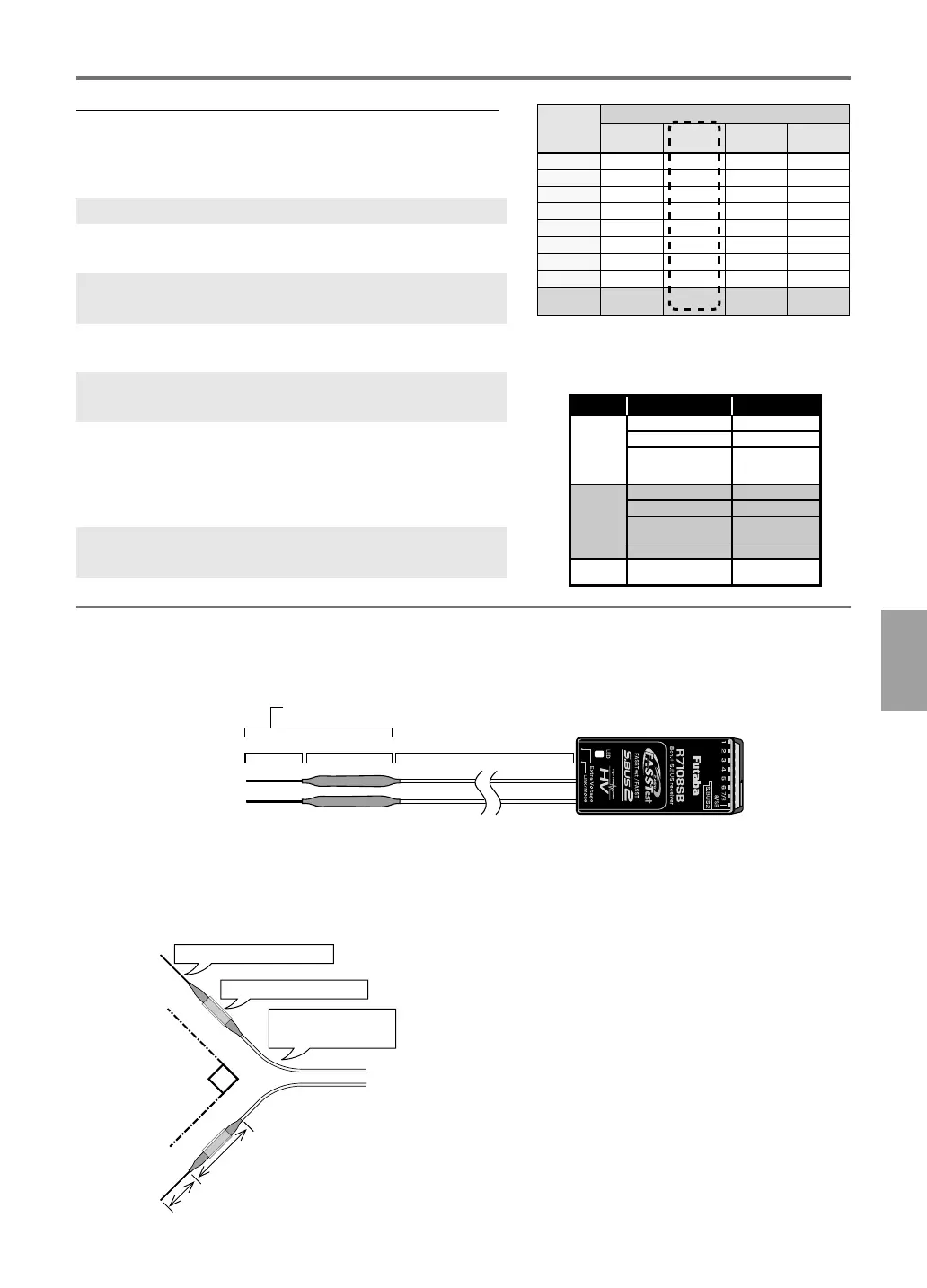
Receiver's Antenna Installation
The R7108SB has two antennas. In order to maximize signal reception and promote safe modeling Futaba
has adopted a diversity antenna system. This allows the receiver to obtain RF signals on both antennas and
y problem-free.
To obtain the best results of the diversity function,
please refer to the following instructions:
1. The two antennas must be kept as straight as
possible. Otherwise it will reduce the effective
range.
2. The two antennas should be placed at 90
degrees to each other.
This is not a critical figure, but the most
important thing is to keep the antennas
away from each other as much as possible.
Larger models can have large metal objects
that can attenuate the RF signal. In this case
the antennas should be placed at both
sides of the model. Then the best RF signal
condition is obtained at any ying attitude.
3. The antennas must be kept away from
conductive materials, such as metal, carbon
and fuel tank by at least a half inch. The
coaxial part of the antennas does not need
to follow these guidelines, but do not bend it
in a tight radius.
4. Keep the antennas away from the motor,
ESC, and other noise sources as much as
possible.
Antenna
*Must be kept as straight as possible.
Coaxial cable
R7108SB Receiver
Sleeve
Antenna
installation
90°
Do not bend the antenna part
Gently bend the coaxial
cable part.
Fix the sleeve to the model
Antenna part
Sleeve
Coaxial cable

 Loading...