G1000 NXi System Maintenance Manual Page 290
King Air 300 Series Revision 1
190-00716-N1
8. If no other EIS gauge tests are needed, reconnect and safety the J103 connector and
reinstall the engine cowling(s).
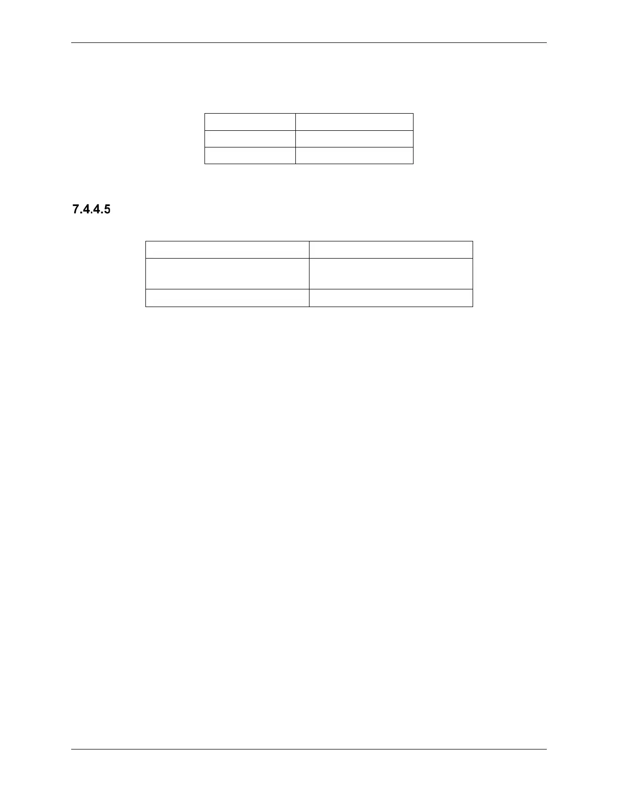
0.00 0 ± 30
66 ± 1 1600 ± 30
Table 7-4, N2 Indication Test Points
Fuel Flow Indication Functional Check
Required test equipment.
Decade Box or equivalent
device
0-1k ohms
If the left engine gauge needs to be tested, perform the following:
1. Disconnect the J104 firewall connector.
2. Apply external power to aircraft and start the G1000 system in normal mode.
3. Inject a 1000 ± 10Ω resistance into the Signal Conditioner by connecting the Decade
box to left engine firewall connector-pins J104-E and J104-F.
4. Inject a 25mV P-P sine wave signal into the Signal Conditioner by connecting the Signal
Generator to the left engine firewall connector-pins J104-Y (HI) and J104-Z (LO).
5. If the test input shows a correct gauge reading within the Indication tolerance in Table
7-5, troubleshoot the fuel flow sensor per the Beechcraft King Air 300 Series
Maintenance Manual.
6. If the test input shows an incorrect gauge reading outside the Indication tolerance in
Table 7-5 perform the following:
a. Check gauge circuit wiring for faults.
b. Replace the Signal Conditioner.
c. Replace GEA 1.
7. If no other EIS gauge tests are needed, reconnect and safety the J104 connector and
reinstall the engine cowling(s).
If the right engine gauge needs to be tested, perform the following:
1. Disconnect the J105 firewall connector.
2. Apply external power to aircraft and start the G1000 system in normal mode.
3. Inject a 1000 ± 10Ω resistance into the Signal Conditioner by connecting the Decade
box to left engine firewall connector-pins J105-E and J105-F.
4. Inject a 25mV P-P sine wave signal into the Signal Conditioner by connecting the Signal
Generator to the left engine firewall connector-pins J105-Y (HI) and J105-Z (LO).
 Loading...