GNS 430 Pilot’s Guide and Reference
10-20
SECTION 10
AUX PAGES
10.4 SETUP 1 PAGE
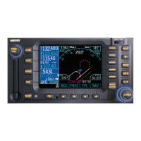
The Setup 1 Page (Figure 10-51) provides access (via
‘menu options’) to airspace alarms, CDI scale adjustment,
an arrival alarm, units of measure settings, position formats,
map datums, and settings for local or UTC time display.
When a menu option is selected, the corresponding page
appears providing access to the various unit settings.
To select a menu option from the Setup 1
Page:
Figure 10-51 Setup 1 Page
Current Page Group
Menu Options (to Select, Highlight
with Cursor and Press the ENT Key)
Position of
Current Page
within Current
Page Group
Number of Pages in
Curr
ent Page Group
1) Press the small right knob momentarily, to
activate the flashing cursor (Figure 10-51).
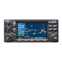
2) Turn the large right knob to select the desired
me
nu option (Figure 10-52), and press the ENT
Key (Figure 10-53).
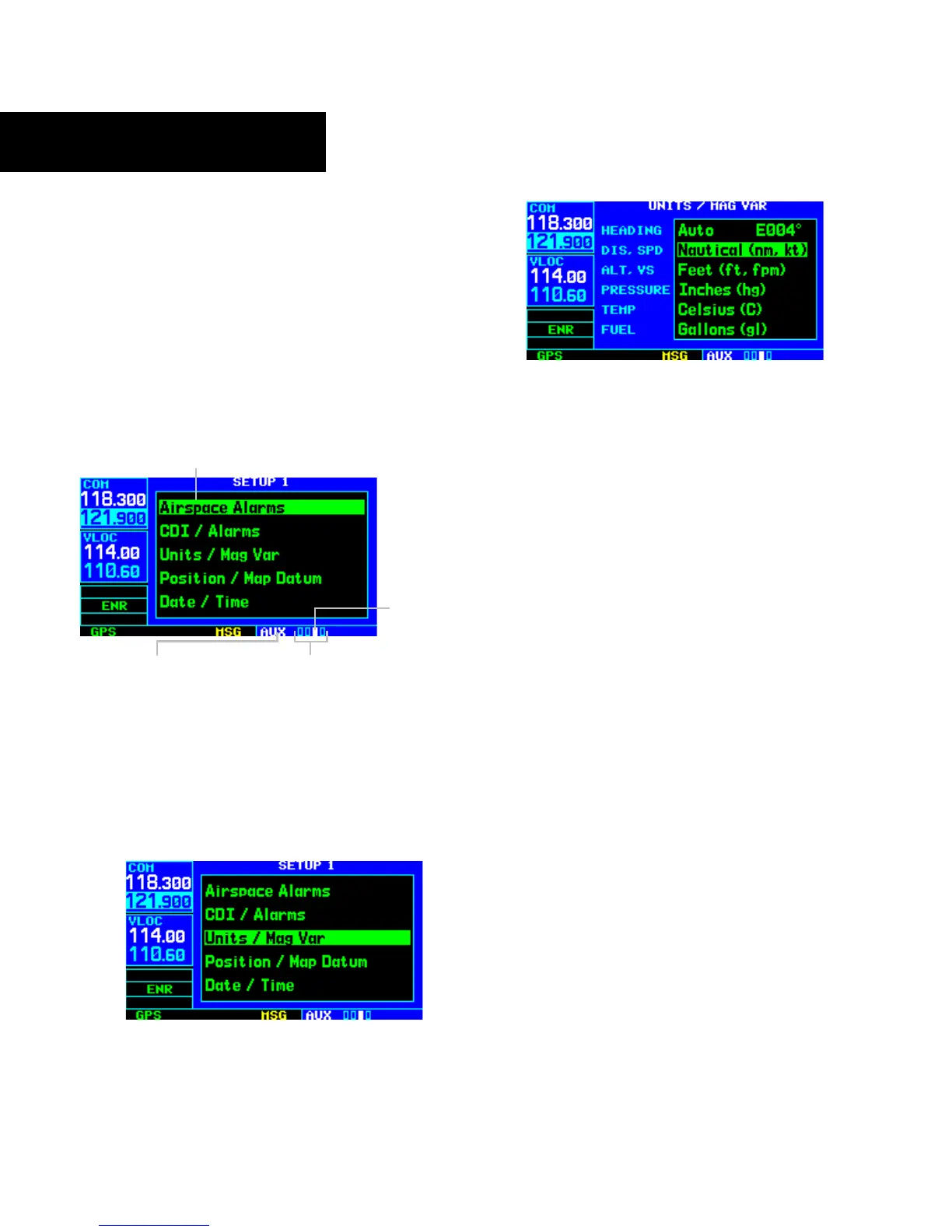
Figure 10-52 ‘Units/Mag Var’ Highlighted
Figure 10-53 Units/Mag Var Page
The following menu options are available:
• ‘Airspace Alarms’ - Allows the pilot to turn the
controlled/special-use airspace message alerts on
or off. This does not affect the alerts listed on the
Nearest Airspace Page or the airspace boundaries
depicted on the Map Page. It simply turns
on/off the war
ning provided when the aircraft is
approaching or near an airspace.
An altitude buffer is also provided which ‘expands’
the vertical range above or below an airspace. For
example, if the buffer is set at 500 feet, and the aircraft
is more than 500 feet above or below an airspace,
the pilot is not notified with an alert message; if
the aircraft is less than 500 feet above or below an
airspace and projected to enter it, the pilot is notified
with an alert message. The default is 200 feet.
• ‘CDI/Alarms’ - Allows the pilot to define the scale
for the GNS 430’s on-screen course deviation
indicator. The scale values represent full scale
deflection for the CDI to either side (Figure
10-54). The default setting is ‘Auto’. At this
setting, the CDI scale is set to 5 nm during the
enroute/oceanic phase of flight. W
ithin 30 nm
of the destination airport the CDI scale gradually
ramps down to 1.0 nm (terminal area). Likewise
when leaving the departure airport the CDI scale
is set to 1.0 nm and gradually ramps UP to 5 nm
beyond 30 nm (from the departure airport).