Specifications
54 560-1025-09 Rev E MX20 Installation Manual
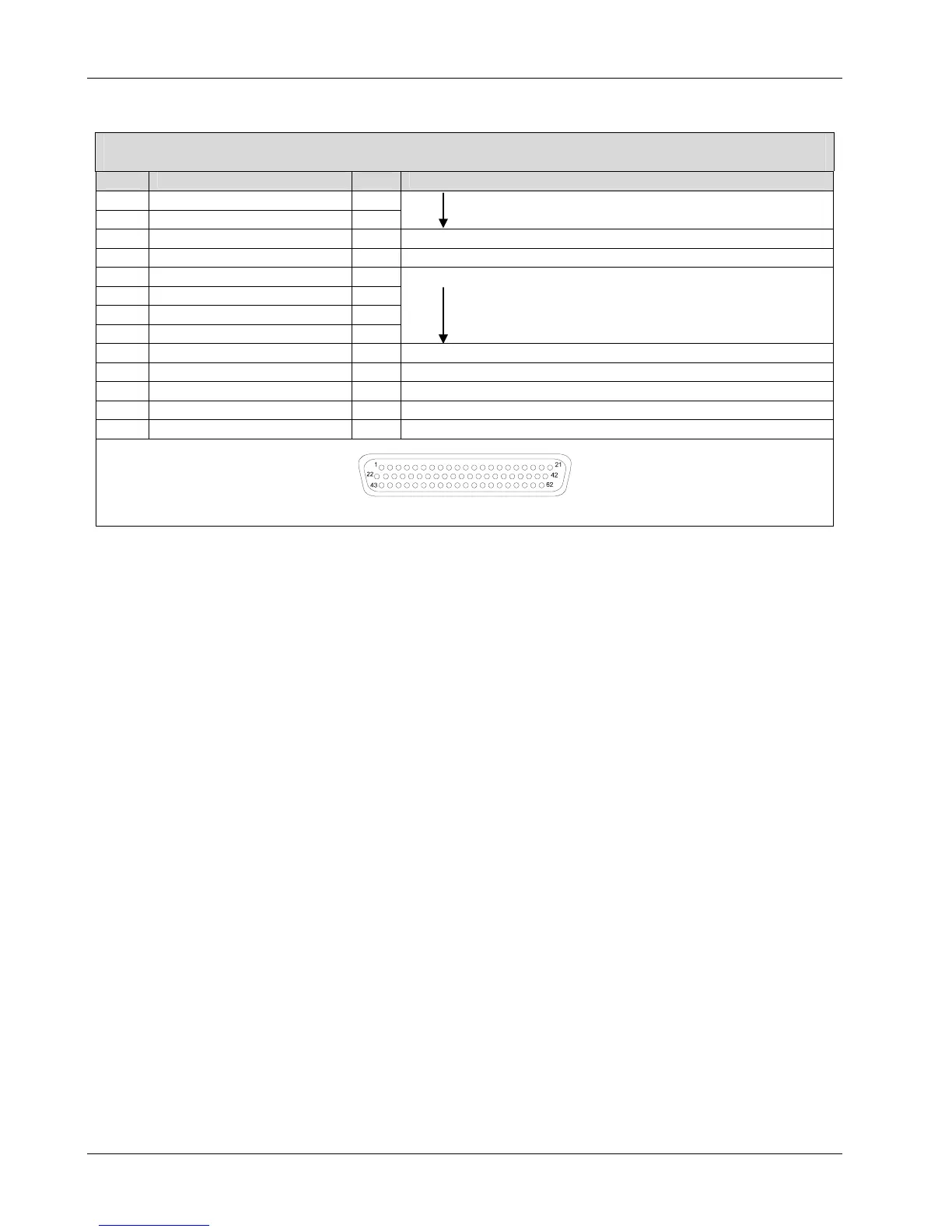
Table 3-5 - MX20 I/O Connector Pin Out (J2) (Cont’d)
Some features listed are not supported at this time
Pin Name I/O Description
50 DISCRETE_IN_1 I
51 +28V I
52 429_OUT_1A O ARINC 429 Output port 1A
53 429_OUT_1B O ARINC 429 Output port 1B
54 561_CLK_IN_B I
55 561_CLK_IN_A I
56 561_SYNC_IN_B I
57 561_SYNC_IN_A I
Reserved
58 429_IN_0B I ARINC 429 Input port 0B
59 429_IN_0A I ARINC 429 Input port 0A
60 429_IN_3B I Reserved
61 429_IN_1A I ARINC 429 Input port 1A
62 429_IN_1B I ARINC 429 Input port 1B
View from rear of unit
3.3 Antenna Requirements
3.3.1 A-33 Antenna
Early production runs of PN 590-1104 were marked with TSO-C129a. This antenna was re-qualified to
TSO-C144 with no changes to the antenna. P/N 590-1104 antennas marked with TSO-C129a identification
are identical to those marked with TSO-C144.
Frequency:...................................................... 1575 MHz
Polarization: ................................................... Right Hand Circular
Axial Ratio: .................................................... 3 dB Max at bore site
Radiation Coverage:....................................... Elevation Angle Minimum Gain
>15º -2.0 dBic
10º -3.0 dBic
5º -4.5 dBic
0º -7.5 dBic
Finish:............................................................. Polyurethane Enamel
Weight: .......................................................... 3.9 oz. (0.11 kg)
Height: ........................................................... 0.61 inches (1.55 cm)
Operating Temperature: ................................ -55°C to +85°C
Operating Altitude: ....................................... 55,000 feet (16,764m) max.