Installation
14 560-1025-09 Rev E MX20 Installation Manual
2.5 Electrical Connections
The MX20 installation kit includes connectors and crimp contacts. Make the crimp connections with a
crimp tool as specified in the Special Tools Required section on page 6. Wires should be 20 to 24 AWG
for the 37-pin connector and 22-30 AWG for the 62-pin connector, unless otherwise specified. Power
and ground wires should be 20 AWG. Shield grounds should be as short as possible and connected to
the grounding lug on the back of the chassis with wire of three inches, or less.
Wiring shall be in accordance with AC 43.13-1B.
All RS-422 or RS-232 connections should be made with twisted pair shielded cable.
All ARINC 453/708 connections should be made with 70 ohm, constant impedance, twisted
pair shielded cable.
All ARINC 429 connections should be made with twisted pair shielded cable.
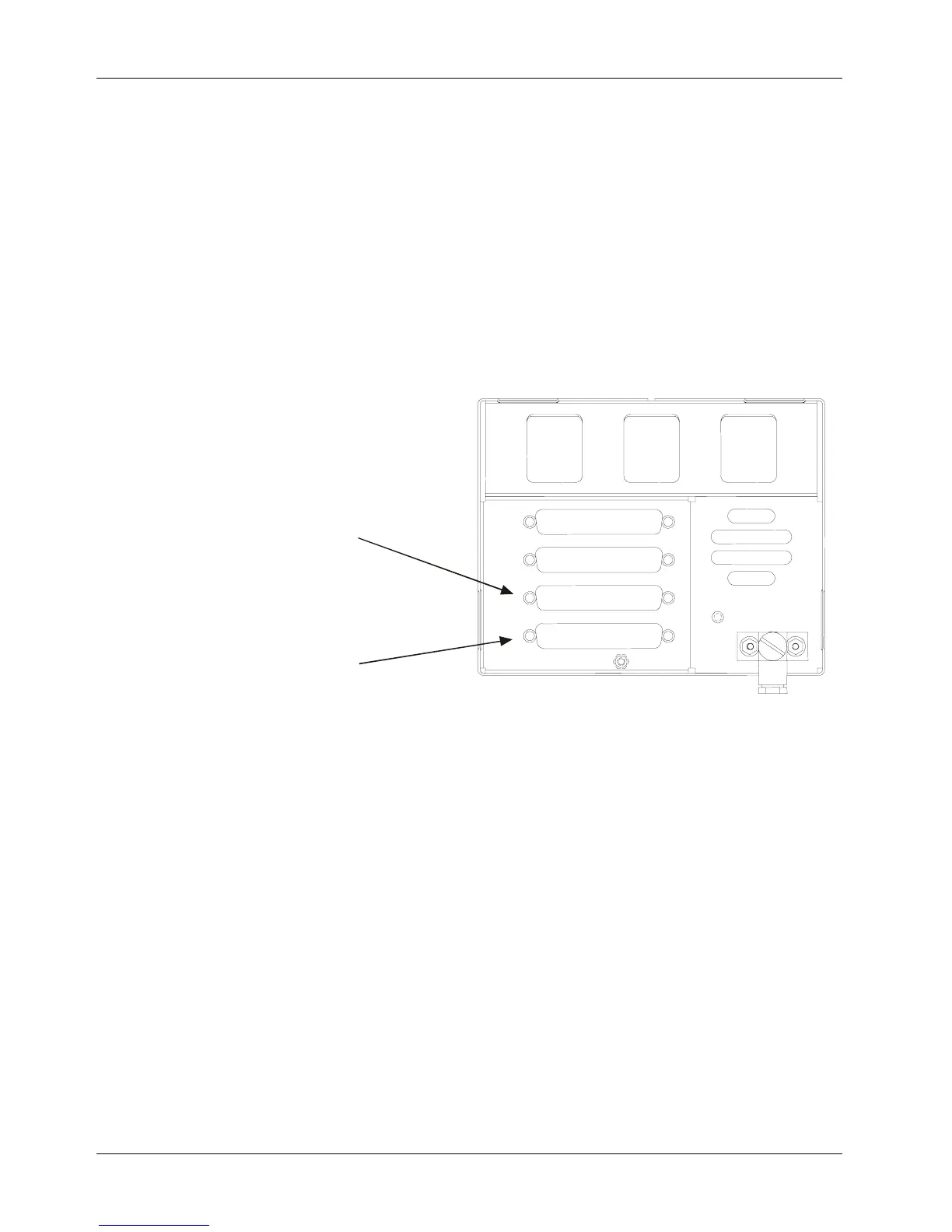
Figure 2-9. Data Port Location
Connector J2
MX20 I/O 62-pin D-Sub
Connector J1
Basic MX20 37-pin D-Sub