111
Advent Commercial Fire System
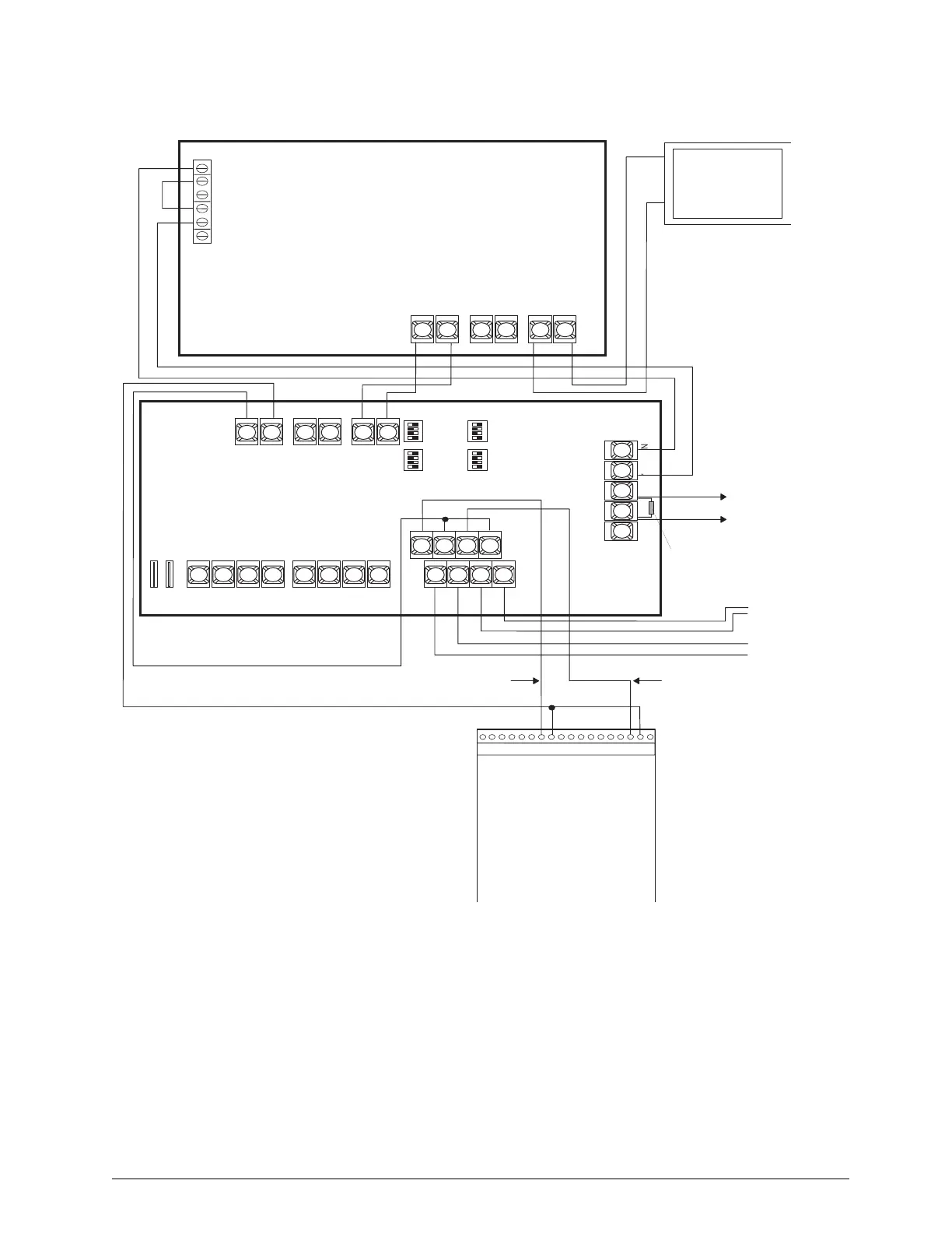
Figure C5. Wiring AL602ITI Power Supply
+ D C + B A T
A C A C
B A T F A I L
N O C N C
A C F A I L
N O C N C
+ O U T 1 + O U T 2
I N 1 +
+ O U T 3 + O U T 4
I N 1 I N 2 +
I N 2
R E T 1 + R E T 1
R E T 2 +
A U X +
N O ' R E M O T E ' C
D C +
N C
C N O
C ' F A U L T '
N C
O U T 1 O U T 3
I N P U T S E L E C T
T E M P O R A L
S T R O B E S Y N C
I N > O U T S Y N C
O U T 2 O U T 4
I N P U T S E L E C T
T E M P O R A L
S T R O B E S Y N C
I N > O U T S Y N C
S W 2 S W 1
1 2 3 4 5 6 7 8 9 1 0 1 1 1 2 1 3 1 4 1 5 1 6 1 7
N O 1
N C 1
C O M 1
+ 1 2 V D C
1 8
N O 2
N C 2
C O M 2
N O 3
N C 3
C O M 3
N O 4
N C 4
C O M 4
G N D
Z O N E 1
Z O N E C O M
B U S A
B U S B
+
+
R E T 2
Refer to AL602ITI
Installation
Instructions For
DIP Switch Settings
Trouble Output
to any Advent Panel
Input or Input Module
Programmed as Zone
Type 96
Listed
2K-OHM EOL
Resistor
PS-12/24-8
or
AL802UL-ADA
Power Supply
PS-12/24-8
or
Logic Board
AL802UL-ADA
(To Logic Board NC)
(To Logic Board C “Fault”)
(To Power Sup Board Bat Fail NC)
(To Power Sup Board AC Fail C)
To IN2 of Next
AL602ITI
To IN1 of Next
AL602ITI
Audible (Horn)
Output
Visual (Strobe)
Output
Transformer
To any Available
Outputs
4 Relay Output Module
(60-770)
(Mounted Inside
Advent Panel Enclosure)