10
Advent Commercial Fire System
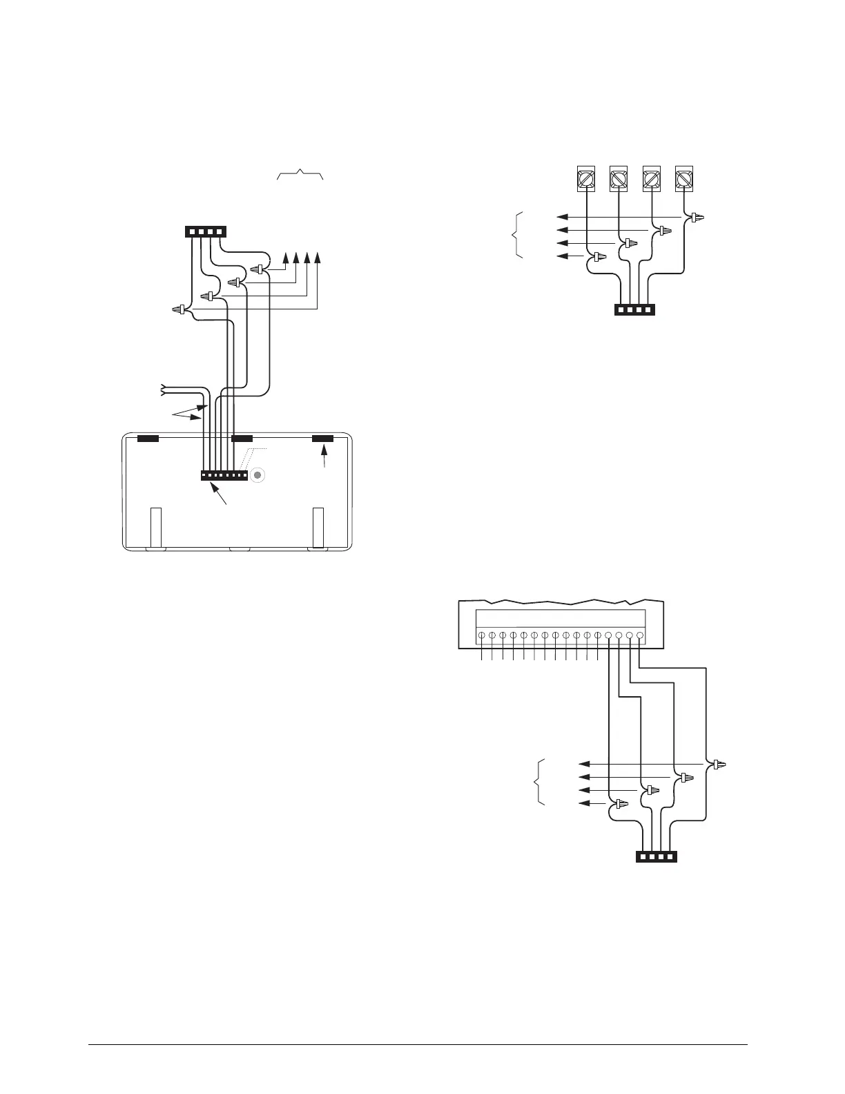
Figure 6. Connecting SuperBus 2000 Alphanumeric
touchpads
SuperBus 2000 Modules
Commercial RF Transceiver Module
Commercial RF Transceiver Module in Plastic Case
(60-821-95)
Commercial RF Transceiver Module in Metal Case
(60-856-95)
Note
For Commercial Fire installations the Commercial Trans-
ceiver Module in the Metal Case (60-856-95) must be
used.
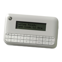
Connect the transceiver to the panel as shown in Figure 7.
Figure 7. Connecting SuperBus 2000 Commercial RF
Transceiver module
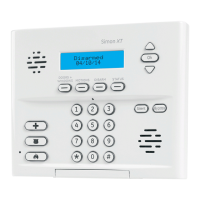
8Z Input Module (60-774)
Connect the SuperBus 2000 8Z Input Module to the panel
as shown in Figure 8. Connect all necessary input wiring
using the Installation Instructions included with the mod-
ule.
Important !
For proper UL 864 compliance, all 8 inputs (terminals 1
through 12) shall be one of the following:
1. Security intrusion connections or,
2. fire device connections.
Combining security and fire connections on these termi-
nals is not approved for UL 864 by the manufacturer.
Figure 8. Connecting a SuperBus 2000 8Z Input
Module
4-Relay Output Module (60-770)
Connect the SuperBus 2000 4-Relay Output Module to the
panel as shown in Figure 9. Connect all necessary output
8543265A.DSF
NOT
USED
YELLOW
TOUCHPAD
WIRING HARNESS
49-430
SPLICE
PANEL SUPERBUS
WIRING
HARNESS 49-462
BLACK (GND)
WHITE (BUS B)
GREEN (BUS A)
RED (+12 VDC)
TO ADDITIONAL
SUPERBUS
TOUCHPADS
AND/OR
MODULES
TAB
SLOT (3)
WIRES FOR HARDWIRE
INPUT OR KEYSWITCH
(SEE SPECIFIC TOUCHPAD
INSTALL INSTRUCTIONS
FOR INFORMATION AND
RESTRICTIONS)
8674G05A.DS
+12
VDC
GND
BUS
A
BUS
B
BLACK
WHITE
GREEN
RED
SUPERBUS COMMERCIAL
RF TRANSCEIVER
MODULE
SPLICE
PANEL SUPERBUS
WIRING
HARNESS 49-462
TO OTHER
SUPERBUS
DEVICES
8543266A.DSF
BLACK
WHITE
GREEN
RED
SPLICE
PANEL SUPERBUS
WIRING
HARNESS 49-462
TO OTHER
SUPERBUS
DEVICES
12345678910111213141516
ZONE COMMON
ZONE 1
ZONE 2
ZONE 3
ZONE 4
ZONE 5
ZONE COMMON
ZONE COMMON
ZONE 6
ZONE 7
ZONE COMMON
ZONE 8