38 GE INFORMATION D20MX INSTRUCTION MANUAL
CHAPTER 2: INSTALLING THE D20MX
Figure 11: Cable to fiber optic daughter card
8. If the D20MX is being installed in a VME chassis, connect the 0 V cable (part number
975-1237):
8.1. Connect the bare end of the 0 V cable wire to the O V connector on the
WESTERM terminal block TB2-9.
8.2. Remove the wire from the lower 0 V connector on the VME backplane and
connect this wire to the male end of the 0 V cable.
8.3. Connect the female end of the 0 V cable to the lower 0 V connector on the VME
backplane.
See Figure 12, “0 V cable connection”.
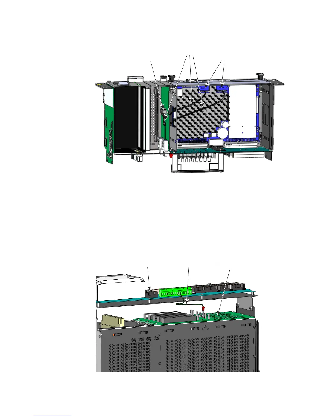
Figure 12: 0 V cable connection
P1 connector on Fiber
optic daughter card
J3 and J4 connectors
on D20MX PCB
Cable
D20 Chassis - view
through top panel
WESTERM D20M+ SS
Termination Panel
D20 VME Chassis
WESTERM D20VME -
VME Bu s Ba ckpla n e
0 V
Cable