– 47 –
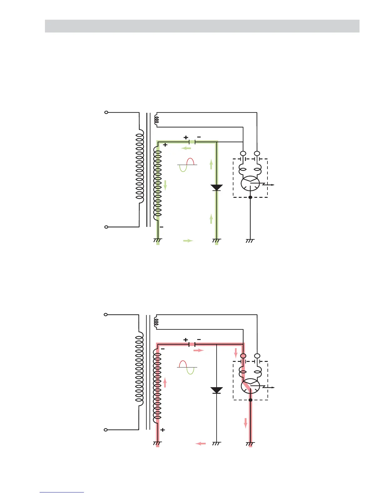
High Voltage Half–Wave Doubler
The half wave voltage doubler circuit consists of the secondary winding of the high voltage transformer, high
voltage diode (rectifi er), and the high voltage capacitor. The high voltage diode allows alternating current (AC)
to fl ow in one direction only and rectifi es it to pulsating direct current (DC).
The high voltage capacitor is able to store energy on one half of the AC cycle and release it on the other half
cycle. During the fi rst half cycle of operation, the secondary winding of the transformer supplies 2000 VAC to
the capacitor. Current fl ows through the diode and returns to the transformer for a complete circuit. This half
cycle of the AC charges the capacitor to approximately 2000 VDC.
During the second half cycle of operation, the current fl ows in the opposite direction, and again supplies
2000 VDC to the circuit. This allows the capacitor to discharge its 2000 VDC on top of the 2000 VDC
generated by the secondary winding, creating an approximate total voltage of negative 4000 VDC.
The negative 4000 VDC causes the magnetron to conduct current and oscillate at 2450 MHz. The fi rst half
cycle and the second half cycle become one complete cycle, repeating with input power frequency at 60 Hz.
Primary
Winding
at 120 VAC
Secondary
Winding at
2000 VDC
Magnetron
Capacitor
Diode
Filament Winding
Primary
Winding
at 120 VAC
Secondary
Winding at
2000 VDC
Magnetron
Capacitor
Diode
Filament Winding